Ring Accelerator Part 3
This is the final part of the Ring Accelerator project. Part 1 and Part 2 were the beginning posts. After receiving the necessary relays to alleviate MOSFET destruction, the new schematic layout is shown here.
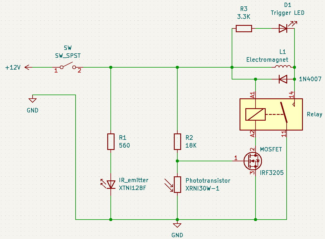
As there are two coils on opposite sides of the ring, the above schematic is duplicated, one for each coil. If there were more coils, each would have its own circuit as shown above. I doubt if I will create a design with additional coils, as two is sufficient to demonstrate the concept to my satisfaction.
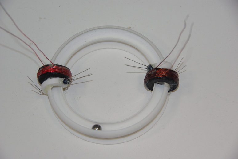
The assembled ring with both sets of coils, emitters and phototransistors in place, ready for wiring. Looking closely, you can notice one lead of each device is longer than the other. For the IR emitter, the anode is longer than the cathode, which goes to ground. The IR phototransistor emitter lead which goes to ground is longer than the collector lead.
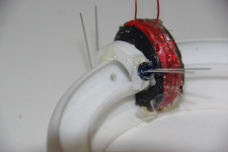
The small hole drilled in the raceway for the phototransistor can be seen in the above image, with the emitter on the right of the holder. The emitter is placed in the holder such that the end is even with the inside of the raceway so as not to impede the ball travel.
Circuit operation is simple and straightforward. When the power is applied, the IR emitter radiates, which is received by the IR phototransistor. This then pulls the MOSFET gate lead low (off). As the ball travels in the raceway and crosses between the two IR devices, the beam is interrupted, which causes the MOSFET gate voltage to rise above saturation (0.8 V). This shorts the MOSFET drain to the source, providing a current path to ground for the relay coil, closing the contacts and providing a path for the electromagnet to energize. This pulls the ball toward the center of the coil, but also clears a path for the IR devices to reconnect, thus shutting off the current for the electromagnet. So, the ball is propelled onward to the next round, where the process is repeated. The relay contacts also provide a return path for the trigger LED which visually indicates the pulse. The reversed-polarity diode across the coil provides a return path for the large pulse generated when the electromagnet is de-energized. This is also called a flyback diode, and acts as a short circuit to dissipate the energy. The dual circuit draws about 40 mA during rest, and around 7 amps during a pulse, as only one circuit is energized at a time. Adding two or more balls to the raceway may double the pulse current if both coils are energized simultaneously. However, this is unlikely, as both coils would have to be matched exactly, and the raceway friction would have to be very small.
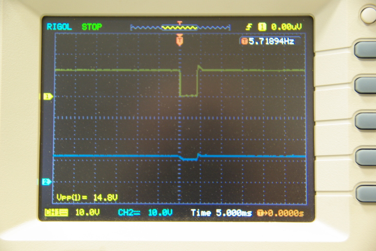
When both coils are engaged, the acceleration is greater than with a single coil. This causes the pulse time for each coil to reduce to < 10 mS. I also notice a slight negative pulse on the other coil, primarily caused by input voltage reduction, as the power supply current goes from a rest current of 38 mV for the entire circuit, to ~7 amperes on the active coil.
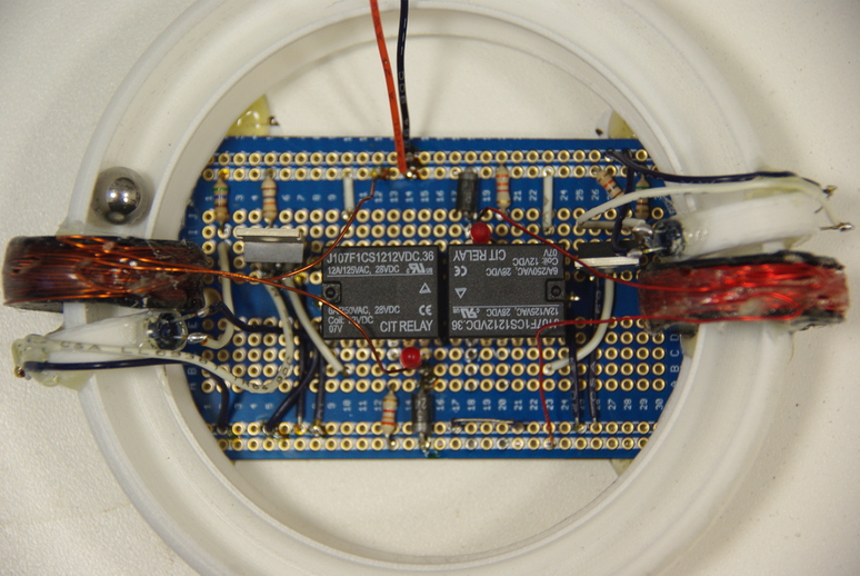
The completed circuit is mounted on a solder breadboard. I briefly entertained the idea of designing a PCB, but decided it was not necessary for a one-off project. The relays I used had the common pole for the contacts offset from a standard 0.100 inch spacing, which was a minor problem as I had to bend the pin out and run a separate wire. The trigger indicator LED and resistor are just eye candy and not really necessary.
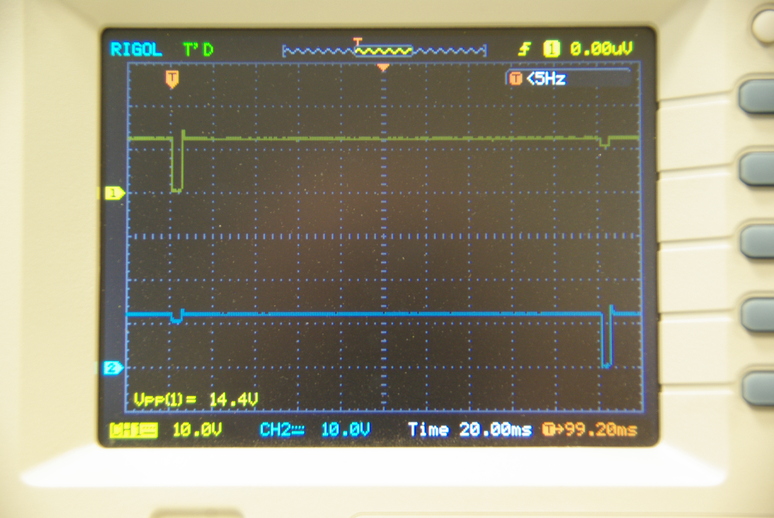
The two coils are engaged ~200 mS apart. The coils are not exactly the same impedance, so each coil imparts a slightly different velocity. As the ring diameter is 100 mm, the ring circumference is 314 mm. So the ball circumnavigates the ring ~375 mS according to the oscilloscope. This means the average velocity is 0.84 meters per second or 2.74 feet per second or 1.87 miles per hour. Adding more coils will increase the velocity.
Not too shabby for a kludged-together device. It seems rather trivial to note that the track doesn’t have to be circular. It could be straight, or oval like a racetrack. Or it could be in a S-configuration with some sort of straight return path. All that would be required would be coils spaced every so often to maintain velocity around the track. The possibilities are endless!
That’s all for this little experiment. Have a great day and may God Bless your life. If you don’t know God and have not accepted Jesus as your Lord and Savior, time is getting really short! “As in the days of Noah…”