Ring Accelerator Part 2
As I mentioned in this post, I am attempting to create a ring accelerator. I have most of the necessary parts now. I decided to use 3/8” steel balls as they are relatively cheap as slingshot ammunition.
As mentioned previously, I decided to use Infrared emitters and phototransistors1 as this should not depend on specific levels of room lighting for reliable operation. However, this did require changing some parts values to compensate. The two-lead IR phototransistor package is identified by the emitter lead being slightly longer than the collector lead. The two-lead IR emitter package has the anode lead longer than the cathode lead.
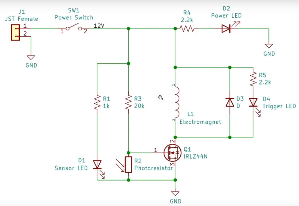
In the above image, R1 is changed to 560 \(\Omega\), R3 to 18 K\(\Omega\). Also, because I am using a miniature LED for the trigger indicator, R5 is changed to 3.3 k\(\Omega\). Also, I discovered that using the MOSFET without a heat sink is a great way to eliminate excess parts. What this means is several things.
- One, the #24 AWG wire is only rated for a bit over 1/2 ampere. This is not normally an issue as the energizing pulse is only around 20 mS in duration.
- Two, the MOSFET heats up really fast with no heat sink. This is caused by the fact that the coil needs about 6 to 7 amperes to give a good stiff kick to the ball to traverse the ring in a timely manner.
- Three, the spool size with #24 wire gives only ~ 1 \(\Omega\) resistance, which at 12 volts, allows 12 amperes current flow. As mentioned in One above, this is not normally an issue.
However, what can happen if the ball lingers between the IR emitter and sensor is the on-time is much longer, which destroys the MOSFET in less than 2 seconds, leaving it fully on. This also holds the ball in the coil, stopping rotation. The answer is a relay to take the current load off the MOSFET.
So what I am currently using is a 12 V relay, with the relay coil connected between the 12 VDC rail and the MOSFET’s drain lead, and energized when the phototransistor goes high, allowing the voltage on the MOSFET’s gate to rise above saturation, about 0.8 VDC. This then allows the relay contacts to complete the inductor’s current path to ground, to kick the ball around the track, on it’s merry way!
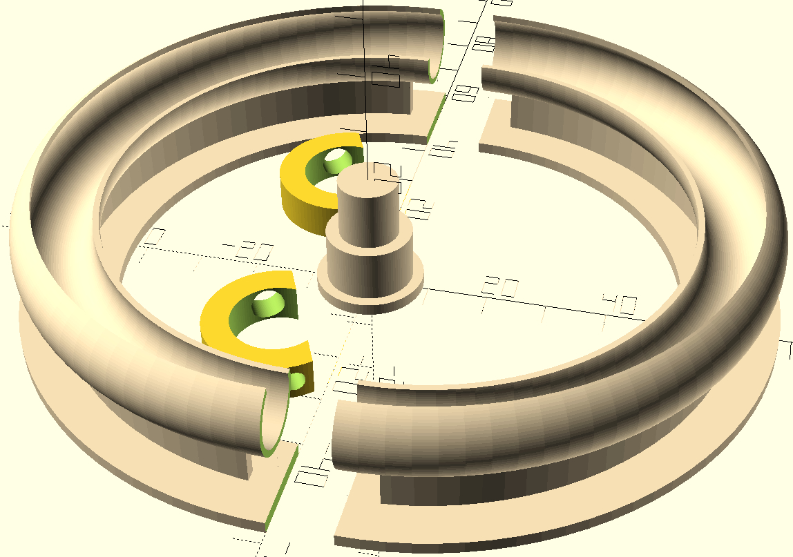
My next attempt is using two coils. I find that winding the coils by hand is not satisfactory, so I will use a bobbin holder (shown in center of below image) and wind the coils using a drill to achieve a layer wound coil which should allow more wire for a slightly greater electromagnetic punch to the ball. And, the winding should look much smoother!
I also redesigned the two-piece track with the base attached which allows easier gluing, thus reducing resistance to the ball’s path around the track. I found trying to hold the track segments aligned with the base while applying hot glue was not the best method to have everything line up for the second track section. So any misalignment created slight bumps which impeded the ball’s progress around the track.
Often, acetone is used to smooth PLA for 3D printed designs, but I don’t have any, so have to use sandpaper for smoothing.
The small pieces shown above inside the ring segments are the mounts for the IR emitters and phototransistors. The packages are different diameters and lengths, so I mounted the larger emitter to the inside just above the ring lip, and drilled a small hole in the lower outside of the track for the phototransistor, the smaller hole presenting less resistance to the ball’s path around the ring. Then, the holder is aligned such that the phototransistor is inline with the hole, which is 7 mm from the wire spool’s edge.
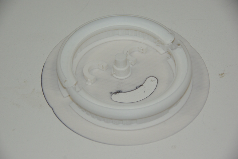
The new design I printed using white PLA just for a change. The above image is before cleaning the finished printout. I also made the IR holders a bit thicker for better support, and to facilitate drilling the hole in the ring for the emitter beam to project through to the phototransistor.
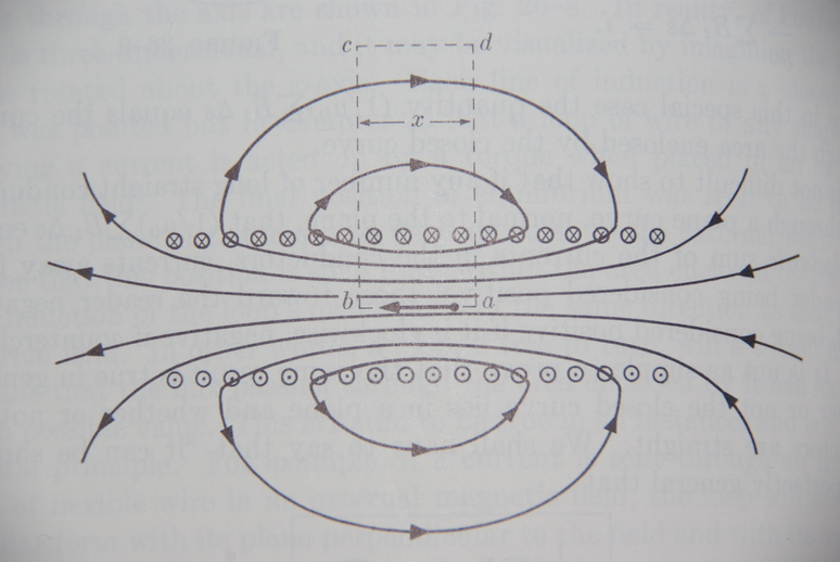
The above representation from (James A. Richards 1962), Page 530, shows the lines of force that grab the ball to propel it on it’s way around the track. The pulse is short so as not to stop the ball in the center of the coil. This timing is directly related to the placement of the IR emitter and phototransistor. The pulse through the coil varies within the range of 10 to 20 mS duration, depending on the speed and the total time the ball disrupts the beam as it passes through, shown in the below image.
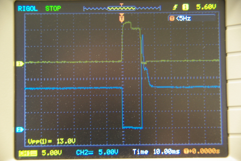
The upper (yellow) trace is the pulse generated by the interval the ball breaks the beam. The drain pulse (blue) is the time the relay energizes the coil to snatch the ball. As the ball leaves the beam, the coil is de-energized so the coil doesn’t have time to stop the ball. The faster the ball travels, the shorter the pulse through the coil.
After testing, preliminary findings seems to indicate black PLA absorbs stray rays better than white PLA for a more positive IR pulse. The pulse width remained about the same, but the MOSFET gate amplitude decreased more rapidly, as the rays reflected more strongly around the steel ball when using white PLA for the raceway. However, the drain pulse which energized the relay remained the same, as the MOSFET gate saturation voltage is 0.8 volts. This may become a factor if the ball speed exceeds the switching time for the gate, which could cause the gate voltage to decrease below saturation too soon. Additionally, one result might be an automatic speed governor, although I doubt the ball would reach such speeds.
The coil bobbin I am using has a winding area about 6.5 mm wide and depth about 7 mm. The inside bobbin diameter is about 15 mm, with a width of 10 mm. The wall thicknesses are about 1 mm, which gives sufficient rigidity.
I wound all the coils except the first using the coil holder shown in the second and third images above. Winding several coils give slightly varying results, as I don’t have a way to count the number of windings when using a drill. Four coils produced give the following results.
| Coil # | Resistance, Ohms | Inductance, mH | Q Factor | Self-resonance, kHz |
|---|---|---|---|---|
| 1 | 1.0 | 0.22 | 14.1 | 1985 |
| 2 | 1.1 | 0.34 | 7.1 | 1519 |
| 3 | 1.2 | 0.37 | 6.2 | 1422 |
| 4 | 1.4 | 0.46 | 5.9 | 1252 |
Note the first coil in the above chart for the Figure of Merit (Q), where the coil was scramble-wound by hand, which caused less wire to fit within the spool. The remaining coils were layer-wound with the drill.
The next installment will have to wait until I can procure some 12 volt relays. So, have a great day and may God Bless you and yours.
References
Footnotes
The IR emitter is SunLED XTNI12BF, the IR phototransistor is SunLED XRNI30W.↩︎