Ring Accelerator Part 1
This post takes a bit of a sidetrack from the usual, as I thought I would experiment with attempting to build a Ring Accelerator. On the other hand, is there anything on this website that could be called usual? What’s your definition?
Anyway, just in the process of acquiring some parts to construct a version, from videos I have watched on the Internet. I know there are several sites that sell ready-made accelerators, but the price seems a bit steep when they can be built with a little ingenuity, and a 3D printer. Of course the electronic parts will have to be acquired, but a well stocked Junk Box helps greatly in that arena!
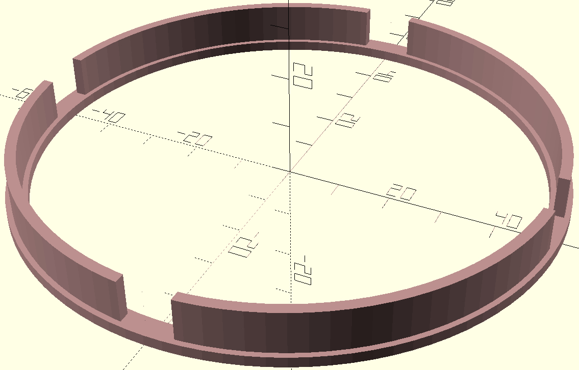
So what we need is a circular raceway for the accelerated object to travel about. In this case, the accelerated object will be a 3/8” steel ball, commonly used for slingshots. The track in this version is about 100 mm diameter, designed and built using OpenSCAD, which is my preferred CAD tool.
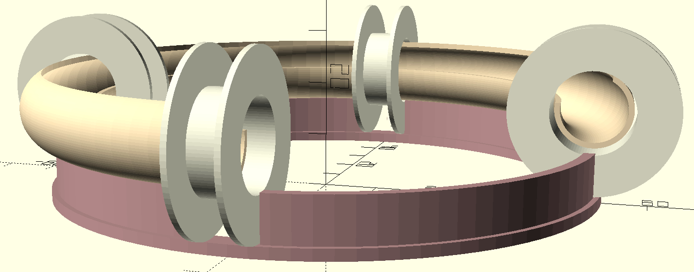
The cutout in the above image is to illustrate the banked track for the ball to travel, without ejecting itself out of the ring. Even though the above image shows four coils, the first iteration will be using only one coil to verify the circuit and basic design will actually perform. From the Internet, I found this circuit, which I will breadboard to verify the values.
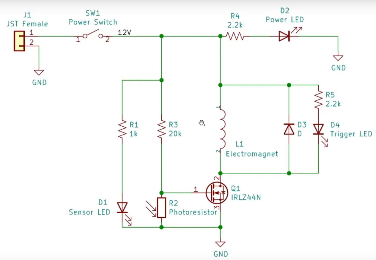
Several parts will deviate from the shown circuit. The MOSFET1 I will use is the International Rectifier IRF3205N, instead of the shown IRLZ244N. They are approximately equivalent, although the 3205 has a higher current rating, and I have several on-hand. Though the values of the sensor LED and photoresistor are not called out in the schematic, I will use an IR emitter and phototransistor, instead of a visible light pair. The phototransistor is the SunLED XRN130W-1 and the emitter the XTNI12BF diode, both available from many places, such as DigiKey. Both operate with a wavelength of 940 nm, in the infrared range.
The wire for the coil(s) will be #24 AWG. I have not decided what impedance I need for the coil, perhaps around 2 \(\Omega\) or so. This should give a pulse of about 6 amps through the MOSFET. The wire is rated at about 1/2 ampere continuous, but the pulse should be short.
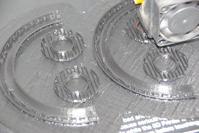
Here we see, during printing, where the supports are built for overhangs and the spool tops.
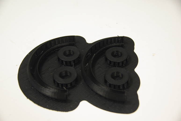
The printed parts coming out of the printer are not ready for prime time, as they need cleaning and the overhang supports removed. The base is printed separately and will be glued onto the raceway after the coil is installed.
The support gives clearance for the coils and helps stabilize the entire structure. And I think that’s about enough for this segment. Check back for more on this project.
God Bless, until next time…
Footnotes
A MOSFET is a metal oxide semiconductor field effect transistor.↩︎