static void pico_rfm_interface() {
  /* setup SPI interface */
  spi_init(spi1, 500 * 1000); // 500 kHz ???
  gpio_set_function(12, GPIO_FUNC_SPI); // SPI1 RX/MISO
  gpio_set_function(14, GPIO_FUNC_SPI); // SPI1 SCK
  gpio_set_function(15, GPIO_FUNC_SPI); // SPI1 TX/MOSI
  //gpio_set_function(13, GPIO_FUNC_SPI);
  // Chip select is active-low
  gpio_init(13);
  gpio_set_dir(13, GPIO_OUT);
  /* Manual reset */
  gpio_init(RESET_PIN);
  gpio_set_dir(RESET_PIN, GPIO_OUT);
  /* Setup GPIOs for RFM69HCW DIO0-DIO5. See header file for actual Pico pins */
  gpio_init(DIO0);
  gpio_init(DIO1);
  gpio_init(DIO2);
  gpio_init(DIO3);
  gpio_init(DIO4);
  gpio_init(DIO5);
  gpio_set_dir(DIO0, GPIO_IN); // necessary ??
  gpio_set_dir(DIO1, GPIO_IN);
  gpio_set_dir(DIO2, GPIO_IN);
  gpio_set_dir(DIO3, GPIO_IN);
  gpio_set_dir(DIO4, GPIO_IN);
  gpio_set_dir(DIO5, GPIO_IN);
}Pico & RFM69HCW Packet Transceiver Part 1
electronics
pico
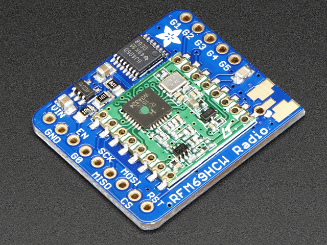
Several weeks ago, I acquired some RFM69HCW Packet Transceiver breakout boards from AdaFruit. These little boards work at 915 MHz1 using the ISM band2, and sport a maximum output of about 100mW (+20 dBm) into a matched antenna. They run on 3.3 v DC; and, including a Pico microcontroller, draw about 32 mA in receive mode and 17 mA in standby mode. Seemed like a nice little radio for links, such as a weather station, or monitor/transmitter for any number of things that could be monitored. In the past, I have used little boards similar, function wise, to these, but they all were continuous operation boards. The beauty of the RFM69HCW is packets! Operationally, they are similar to the LoRa series of radios, but are more suited to local or private interlinks. A 3.3 volt regulator and level shifter are built onto the breakout board, so the inputs and outputs can handle 3-5V DC power and logic. However, using the Pico as a microcontroller, which supplies 3.3 volts, it is a no-brainer to run it on the same.
Now came the fun part! Trying to make it do something useful… There are several packages and libraries available for this board. such as the RadioHead libraries, the LowPowerLabs libraries; these pages are linked on the AdaFruit Using page. For the quick checkout, a CircuitPython library from AdaFruit is handy, and provides a .uf2 file to load onto the Pico board. Having done that, the Pico then reboots and shows up as CIRCUITPY in the directory. Editing the code.py file on that drive allows modification and operation changes.
Ultimately, I installed the CircuitPython files to verify the boards worked. I managed to blow one up by plugging/unplugging from the breadboard, before I soldered them onto a more permanent solution. The next step was making them do more than send packets back and forth between the two I’ve built so far. Since I am not very familiar with Python or CircuitPython, I wanted to use C++. As Python is an interpreted language, and C++ is compiled, C++ is many times faster. I don’t need that speed, but it just made sense, and in the process, I’ve learned loads about classes, functions, constants and vectors.
Before I go any further, I brought out all the breakout board connections to the Pico to allow for future changes and expansions. What may explain it better is the Pico initialization procedure. The code to do the setup I have is this.
I’m pretty sure the last six lines are not really necessary, but I did it that way to be sure, and not have issues while I’m trying to solve other more pressing problems. Some of the RFM69HCW IRQ interrupts default to output on DIO0. In any case, let’s move on to the available libraries.
And that’s where I started running into problems. A couple of weeks of problems. I looked at both the libraries mentioned above, but found them way too complicated for simple functions. I did manage to use parts of both to come up with my vastly simplified files to use. For my purpose, I didn’t need all the bells and whistles those fine libraries provided. So I modified the register file, added some, deleted some, and changed a few constant descriptions. As for the .cpp files that accessed the header files, both were too much, way overkill. C++ is a hobby for me; I am not a professional programmer by any means. In short, there are gaps in what I know about C++ classes and structures. I attempted to validate some parts, but finally abandoned that path for a more simpler approach. That solution was recreate the CircuitPython functionality (as I knew those routines worked) in C++ using functions. Some functions were fairly simple, some difficult. Ultimately, I settled on four files, main program (newRFM69.cpp), functions (newRFM69fun.cpp), header file (newRFM69.h) and register definitions (RMF69reg.h).
For the main program, I selected the switch/case approach. That was when I discovered that setting variables in case statements where the variable may have different values between cases, or not be set at all, is a no-no. The solution to that issue was placing the statements in curly brackets. That quickly became too complicated and messy, so I moved the statements into a function to simplify the case structure. Before that issue, and in the newly-created function, I had headaches using the getline() statement, as it was not lively or responsive. That, I discovered, was caused by a prior cin statement buffer still containing characters, fixed by the cin.ignore() statement. This issue kept me pulling my hair out for several days, before I finally got it working correctly. What was really frustrating was the same statements worked perfectly in their own standalone file.3 On the output side, it would simply refuse to recognize the newline character as the end of character entry, so I eventually used the “|” character to end the line. Those statements look like this.
cout << "1) Send default, 2) Send new: " << endl;
  cin >> msg;
  cin.ignore(0, '\n'); // strip 'cin' of '\n'
  if(msg == 2) {
    string messageNew; // container for new message
    cout << "Type new message, end input with '|'" << endl;
    getline(cin, messageNew, '|'); // refuses to detect '\n'
    cout << endl; // clear buffer
    message = messageNew; // replace original with new message
    }
  cout << "\nNew message: " << message << endl;
That was a very frustrating few days, as most online answers consisted of, “this is how it works,” except it wasn’t! Seems many programmers can explain how it works from a structure/format viewpoint, but pretty shy on input when it does not work. CAVEAT: Of course, part of the problem is most questions found online are different from issues I may be having with my code, so it is a matter of finding something that can be gleaned from many question/answer investigations. I don’t care to post questions that are most likely already answered, especially as forming a good question is as hard as “pulling hen’s teeth!” It’s also sometimes difficult to weed out wrong answers and opinions from good answers. Especially when the snippets of code really pertains to a different question from yours.
So, for now, the functions I am using support this menu of operations.
 static void showmenu() {
    cout << "\nPlease enter your choice, 1, 2, 3, 4, 5, 6, 7, 8 or 9:\n"
        "1) Show Registers          2) Read Frequency\n"
        "3) Set Output Power        4) Send Message\n"
        "5) Clear Screen            6) Receive Mode\n"
        "7) Test XMTR Output        8) Reset Destination\n"
        "9) QUIT\n";
}
A couple of items need clarification. Firstly, #8 allows the user to change the message’s recipient, if there may be several nodes in the network. The option for sender is set on program boot-up. The other (#3) is because there are many power level options available on the RFM69HCW. There are three main registers for power, one allows setting a dBm output level from 0 to 31. This is OR’d with (in various combinations) PA0, PA1, PA2 and two boost registers, giving different power levels from (according to specs) -18 dBm to the maximum of +20 dBm. Also thrown into the mix is required setting of the overcurrent protection register, which must be turned off if power levels are above 18 dBm. Reading and digesting the datasheet is a must to decipher the functionality of this powerful chip. For example, this routine gives data to assist in selecting the desired power output.
    write_register(REG_OCP,RF_OCP_ON); // over current protection on for < +18 dBm
    unsigned t1 = 32; // typed 'unsigned' to prevent 'char' converted to ascii
    uint8_t final = 0x00;
    uint8_t pa0,pa1,pa12,paX;
    uint8_t PA0_ON,PA1_ON,PA2_ON;
    while(t1 >31) {
        cout << "\nEnter dBm power level, digit(0-31): ";
        cin >> t1; // get the 'output power setting.'
    }
    int dBm0 = -18+t1, dBm1 = -18+t1, dBm12 = -14+t1, dBmPA = -11+t1;
    final = t1; // re-type as uint8_t
    pa0 = PA0_ON | final; // OR constant with value
    pa1 = PA1_ON | (final & 0xf0); // OR constant with value
    pa12 = (PA2_ON | PA1_ON) | (final & 0xF0); // both PA registers on.
    paX = (PA2_ON | PA1_ON) | (final & 0xF0); // both PA registers on.
    //cout << "Final: " << static_cast<int>(final) << ", [integer]." << endl; // decimal
    //cout << "Final: 0x" << hex << static_cast<int>(final) << ", [hex]." << endl; // hex
    cout << "Giving the following output power levels:" << endl;
    cout << "    PA0 on: 0x" << hex << static_cast<int>(pa0) << " " << dec << dBm0 << " dBm." << endl; // hex
    cout << "    PA1 on: 0x" << hex << static_cast<int>(pa1) << " " << dec << dBm1 << " dBm." << endl; // hex
    cout << "    PA1/PA2 on: 0x" << hex << static_cast<int>(pa12) << " " << dec << dBm12 << " dBm." << endl; // hex
    cout << "    PA1/PA2/Amps on: 0x" << hex << static_cast<int>(paX) << " " << dec << dBmPA << " dBm." << endl; // hex
This post is lengthy enough. Look for more in Part 2. God Bless all who believe in Him. If you don’t know Him, time is getting short… There’s no time like the present. I know of a close neighbor who finally accepted Jesus the penultimate day before he passed. Praise God!
Footnotes
Another version outputs in the 70 cm USA Amateur Radio Band.↩︎
The Industrial, Scientific, Medical band is for low power devices primarily used for experimentation purposes. See this link for more detail.↩︎
During development, I like to take a particular function and verify it in its own program before moving the statements to a larger main program. For Linux the command for that looks like this: g++ filename.cpp -o filename.out.↩︎