Pico Remote Weather Station
Similar to this post, I have decided to construct a remote weather station. I will place the remote station away from any buildings, structures or tall trees. This means the station will be about 100 feet from the receiver. How do I get the signal?
Well, I am using two RFM69HCW Packet transceivers, one as the transmitter and the other as the receiver. These are supposed to be good for a distance of a maximum of 500 meters (under perfect unobstructed line-of-sight conditions.) I have not tested the range that far. However, they will work through numerous walls, both wood and metal, to a distance of 100 meters. That, I have tested.
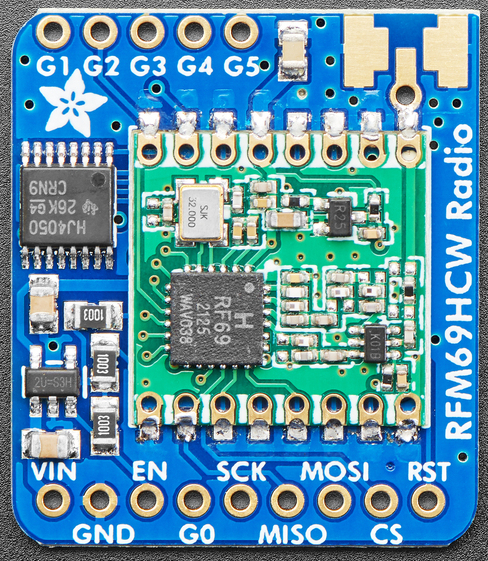
Notice the solder pads at the upper right of the image. I soldered a SMA1 jack here for the antenna. You can solder a short wire here, but transmission distance will be poor. Here is a short list of the main parts.
- One (or more) Raspberry Pico microcontroller,
- Two RFM69HCW 915 MHz Packet Transceivers; also see this post,
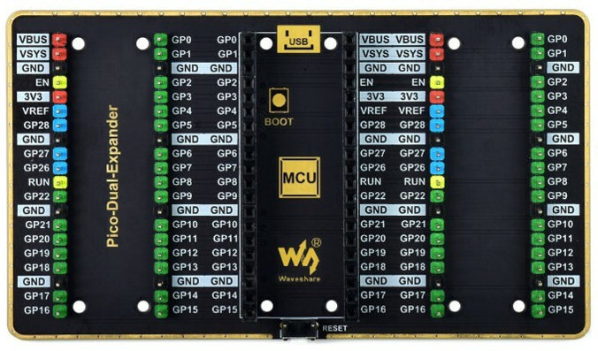
- One Dual GPIO Expander board,
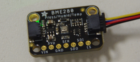
- One BME280 Temp/Humid/Press Sensor,
- One Pico Display Pack 2.8”,
- Two 1/4 wave vertical antennas for reception and transmission.
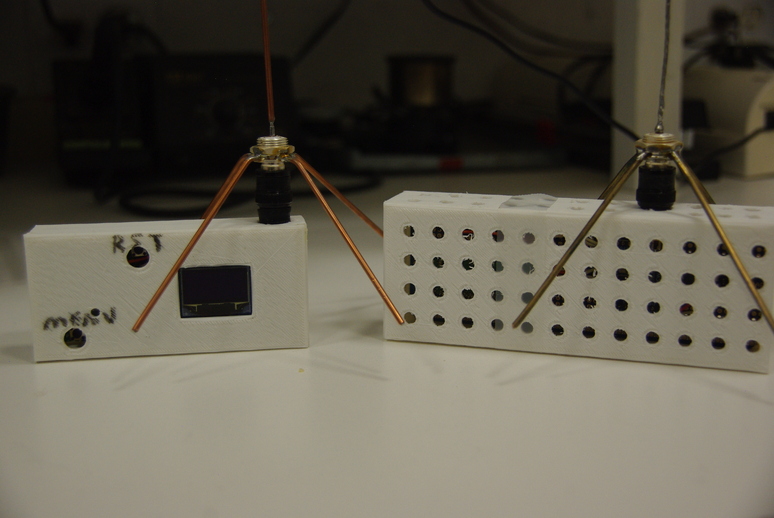
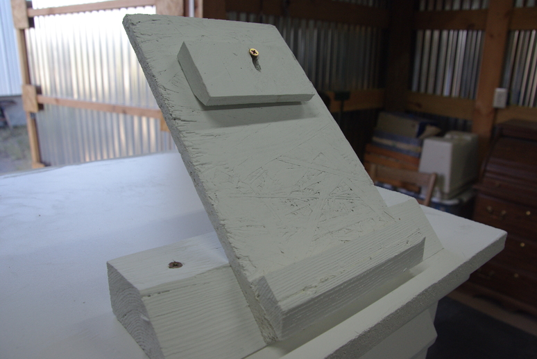
Plenty of holes were designed into the transmitter box allowing free air flow around the BME280 sensor. Notice the tiny display on this prototype receiver model. It is a OLED 128x64 display. For older eyes, reading glasses are required! More on this later.
The antennas are homemade using a standard BNC2 jack, with the length of the antenna element at about 3 inches, or 76 mm. The four radials are soldered onto the jack and bent down at about a 45o angle, which moves the antenna impedance closer to 50 \(\Omega\). Flattening the ends of the radials and clamping with the nut before soldering gives better mechanical stability. I have used copper-coated steel brazing rods, brass brazing rods with the flux removed and twisted copper wire for the antennas. All work Fine.
Fine tuning is done with the Nano VNA V2 Plus 4 vector network analyzer set at a center frequency of 915 MHz. The antennas are connected to the SMA jack with a SMA male to BNC male adapter from Signal Stuff. They are a lot sturdier than many adapters available from offshore businesses, and according to the website, they are Made in the USA.
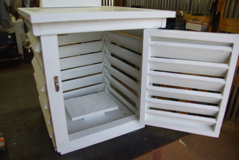
The Stevenson cage (also called Stevenson screen) will be mounted about four feet above ground, with the door facing North, so the Sun will not hit the sensor. For casual home-based usage, this is not too important. However, if the readings are to remain accurate, especially for time-based readings, or uploading to the Internet, this is important. The entire box, including the solar cell mounting, is made with scrap lumber.
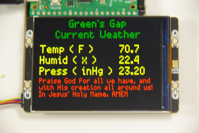
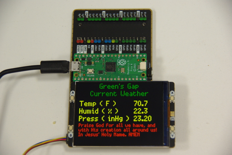
The new bigger display is the Pico Display Pack 2.8”, an IPS LCD3 with a resolution of 320x240 pixels.
The Raspberry Pico plugs directly into the back of the display for a rather compact package. However, therein lies the rub. Access to free pins is rather difficult with this configuration. The display takes up a lot of the pins, leaving sparse pins to be used by the RFM69HCW transceiver. Also, the SPI0 slice, used by the LCD, seems to conflict with using other RFM69HCW functions that are on free pins that correspond to that slice. So, to use any free pins, I opted to use a dual expander board, which does allow access to all pins.
That’s when I discovered a dearth of pins available for the transceiver. So now, I am exploring having the receiver Pico talking to another Pico connected to the display, thereby sending the weather data from the transmitter, through the receiver, to the display’s Pico. This is a work in progress!
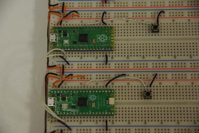
The two Picos are communicating via I2C4 and sending messages. Now, I have to determine how to retrieve the transmitted message, and send it to the display. I want it to look similar to this display, nice and large!
And with that, I will end this post. I will continue the adventure in part 2. For now, That’s All Folks!. We thank God for having the means and knowledge to experiment with these micro-controllers, and we thank Him for His guidance as we go through life!
Footnotes
SMA is SubMiniature versionA, commonly used in microwave systems.↩︎
BNC is Bayonet Neill-Concelman, used to about 2 GHz.↩︎
IPS LCD is In-Plane Switching, a screen technology for Liquid Crystal Displays.↩︎
I2C is Inter-Integrated Circuit, a synchronous, multi-controller/multi-target, single-ended, serial communication bus.↩︎