Recently I have been playing around with the latest embedded microcontrollers I have acquired for experimentation, the Raspberry Pico and the Pimoroni Tiny2040 boards. Both have the RP2040 chip, which is a dual core Cortex M0+ processor running up to 133 MHz. The Pico is a 40-pin breakout board and the Tiny2040 is on a 16-pin breakout board.
The post I reference above has more info on the boards. This post is around my experience with trying to get them to talk to one another. Firstly, I wanted to set up an easy bare-bones cmake file that can be used on any project, with modifications. The pico-examples subdirectory as downloaded from GitHub works by compiling all the examples, which makes is a bit hard and non-intuitive for new files or modifications. This post will attempt to clarify how I modified them for easier creation of new projects. The example described here does the following basic functions.
Using a Pico, detect an input (supplied by a pushbutton),
light a LED as a visual signal,
send a message over USB UART to a computer (Raspberry Pi4),
and key an output (emulating a remote signal).
This signal is then detected by the Pimoroni Tiny2040,
which keys a LED as a visual signal,
and also sends a message via Serial UART to a computer.
Cmake
The CMakeLists.txt file sets up the other files needed for cmake to bring in the libraries needed to assemble the C++ file into a bare-metal.uf2 file which is dropped onto either microcontroller.
First, I create a directory that will contain all the particular files for the project. The basic CMakeLists.txt file may look like this.
Code
cmake_minimum_required(VERSION 3.18)include(pico_sdk_import.cmake)set(CMAKE_C_STANDARD 11)set(CMAKE_CXX_STANDARD 17)pico_sdk_init()project(button C CXX ASM)add_executable(button button.c )# pull in common dependenciestarget_link_libraries(button pico_stdlib)# create map/bin/hex file etc.pico_add_extra_outputs(button)
Not all commands are necessary to make it work, but I left what you see for a reference. The documentation on the Pico website has much more details that explain each line. For starting out, and for simplicity, these two lines in a CMakeLists.txt file activate all the UARTs, but make a huge file.
Code
pico_enable_stdio_usb(remote_receive 1) # Serial output via USBpico_enable_stdio_uart(remote_receive 1) # Serial output via UART
On the Tiny2040, I chose to use Serial UART1 for a smaller file (more below). From the project’s directory, I start as so.
Code
mkdir build && cd buildcmake ..
This creates the necessary files and attaches all required libraries. It also creates a Makefile in the build directory for the next step.
Code
make -j 4
The -j 4 uses all four cores of the Raspberry Pi 4 to speed things up a bit, but is not really necessary. You will end up with many files, but the one for dropping onto the Pico is the button.uf2 file. Plugging the USB cable into the Pico while holding the BOOTSEL button will cause the Pico to be seen as a flash drive, ready for dragging and dropping the button.uf2 file onto. This then causes the Pico to reboot and run your program. If the Pico is powered by a breadboard, temporarily disconnect the Pico’s power.
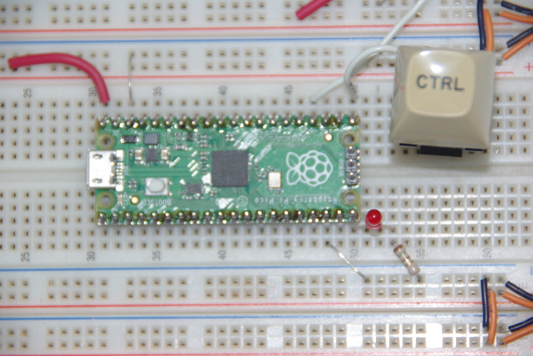
Pico Connections.
Shown above are the connections for the Pico. 5VDC power (pin40) is the upper left red wire with the ground (pin38) next. Output for a remote connection is GP18 (pin24) and the normally-open (NO) pushbutton is connected to GP16 (pin21). Pulling GP16 internally high eliminates a pull-up resistor on the switch. The LED is connected to GP15 (pin20) with a 150 ohm resistor to ground. Another ground wire is on pin18, but is not necessary for this circuit. Below is the button.c file for the Pico board.
Code
#include <stdio.h>#include "pico/stdlib.h"#include "hardware/gpio.h"#include "pico/binary_info.h"#define LAMP 15 // This is actual GP15, physical pin 20#define BUTTON 16 // Button on GP16, physical pin 21#define LINK 18 // Signal output to key something, physical pin 24int main() { /* Use 'sudo picotool info -af' to see these four lines */bi_decl(bi_program_description("Button input (low) to flash LED + UART output.")); bi_decl(bi_program_version_string("0.002"));bi_decl(bi_1pin_with_name(LAMP, "Off-board LED (physical pin 20) w/150 Ohm Resistor to gnd."));bi_decl(bi_1pin_with_name(BUTTON, "Switch press grounds input (physical pin 21)."));stdio_init_all(); // ???gpio_init(LAMP); // initialize GP15 for LEDgpio_set_dir(LAMP, GPIO_OUT); // set as output pingpio_init(LINK); // initialize gP18 for output signalgpio_set_dir(LINK, GPIO_OUT); // output directiongpio_init(BUTTON); // initialize GP16 for buttongpio_set_dir(BUTTON, GPIO_IN); // set as input pin// We are using the button to pull down to 0v when pressed, so ensure that when// unpressed, it uses internal pull ups. Otherwise when unpressed, the input will// be floating.gpio_pull_up(BUTTON); // use internal pull-up to eliminate 150 ohm resistor while (1) { // between 3.3V pin 36 to switch.if (!gpio_get(BUTTON)) { //'if' loop runs on button press (low),gpio_put(LINK, 1); // link highgpio_put(LAMP, 1); // Lamp lightsputs("WARNING: Button is pressed!\n"); } else { gpio_put(LAMP, 0); // lamp normally offgpio_put(LINK, 0); // link normally low } }}
The comments should explain each line enough to determine operation, so I will not elaborate further. This code is not really efficient, but this is how I got it to work for my learning process. The following will open a terminal for receiving output.
Code
minicom -b 115200-o -D /dev/ttyACM0
The next section will explain the Pimoroni Tiny2040 playing the part as a remote receiver of the Pico’s output. There are many circuit modules available from places like SparkFun.com which are low power transmitter/receiver pairs for sending and receiving remote signals and are relatively easy to use via UARTs.
Tiny2040
The Pimoroni Tiny2040 has four times the flash memory of the Pico, and is the size of a postage stamp. Great for embedded applications. I’ve heard of folks using them for colorful badges and such, with a LCD display for a message. In this case I am using it as a receiver to simulate receiving a remote signal. That signal is nothing more than a high from the Pico through a simple jumper wire.
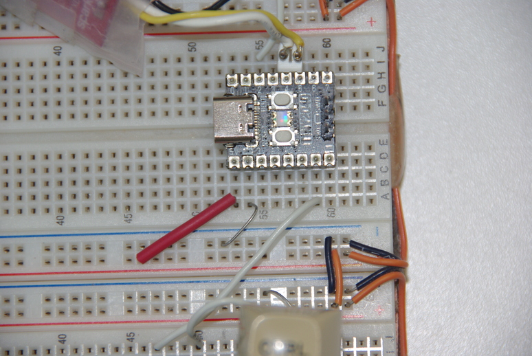
Simulated signal receiver.
Power (5VDC) is supplied by the red wire to pin 1 (VBUS), with ground next to it on pin 2. The white wire from the Pico supplies a high signal to pin 7 (GP26). That signal then keys the UART1 to send out a message to a computer, but also send a positive signal to a LED connected to pin 14 (GP2). A 150 ohm resistor connects the LED to ground. One thing to note is the Pico and Tiny2040 boards want a logic 3.3V signal, not 5 V. Most receiver/transmitter pairs operate with 5V logic signals, so a level converter may be required in real life. I don’t have one so am reluctant to connect those to these boards yet. The boards may tolerate high signals for a while, but I can’t think it would be good for longevity.
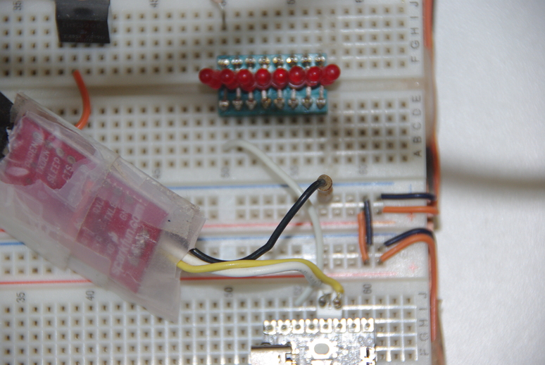
FTDI USB to UART adapter.
Both the Pico and Tiny2 don’t have the serial UART1 activated by default. The standard examples enable only the UART0s, so a few extra steps are necessary. I wished to connect to UART1 on the Tiny2040 although I tested the UART0 connection. The yellow wire above is the FTDI RX (to GP4) and the white TX (to GP5), with the black wire grounded. The plastic is merely to prevent unwanted shorts to components. As mentioned above, my cmake file doesn’t contain the lines to activate USB or serial UARTs. So that requires the file to explicitly activate the UART1.
Code
#include <stdio.h>#include "pico/stdlib.h"#include "hardware/gpio.h"#include "pico/binary_info.h"#define INPUT 26 // This is GP26, physical pin 7#define OUTPUT 2 // LED on GP2, physical pin 14int main() { /* Use 'sudo picotool info -af' to see these four lines */bi_decl(bi_program_description("Tiny2040: Remote INPUT (high) to set OUTPUT (high)")); bi_decl(bi_program_version_string("0.003 using UART1"));bi_decl(bi_1pin_with_name(INPUT, "External input."));bi_decl(bi_1pin_with_name(OUTPUT, "Positive input makes this go high."));//stdio_init_all(); // set UART outputs + all others. place B4 other inits.// doing this here instead of in'CMakeLists.txt' file makes smaller file size.uart_init(uart1, 115200); // initialize UART1 on tiny2040gpio_set_function(4, GPIO_FUNC_UART); // set TX function on pins GP4gpio_set_function(5, GPIO_FUNC_UART); // set RX function on pins GP5gpio_init(OUTPUT); // initialize GP0 for LED outputgpio_set_dir(OUTPUT, GPIO_OUT); // output directiongpio_init(INPUT); // initialize GP26 for remote inputgpio_set_dir(INPUT, GPIO_IN); // set as input pinwhile (1) { // between 3.3V pin 36 to switch.if (gpio_get(INPUT)) { //'if' loop runs on high inputgpio_put(OUTPUT, 1); // output high (on)uart_puts(uart1, "WARNING: Button is pressed!\n\r"); // needs CR:'\r' } else { gpio_put(OUTPUT, 0); // output low (off) } }}
The three lines to activate UART1 are:
Code
uart_init(uart1, 115200); // initialize UART1 on tiny2040gpio_set_function(4, GPIO_FUNC_UART); // set TX function on pins GP4gpio_set_function(5, GPIO_FUNC_UART); // set RX function on pins GP5
The difference in file size is from ~40Kb down to ~15Kb. That’s a big difference for an embedded microcontroller where memory may be tight. Unlike the Pico, the Tiny2040 board has to be in flash memory mode for the file description to be read (using picotool). Those are the lines starting with bi_decl().
I’m having a great time exploring these two microcontroller boards. Hope you enjoy them also if you decide to try them in your project. Have a great day and may God watch over you and yours. If you don’t know Jesus as your personal Lord and Savior, there’s no time like the present. Time is getting short!