Pico Arbitrary Waveform Generator
Since the Raspberry Pico came out, makers and experimenters have found useful and unique ways to apply this very powerful microcontroller. One of those ways is as a arbitrary waveform generator (AWG). This is another name for a function generator, but with more flexibility. I don’t currently have either, as I left many pieces of homemade gear back when we moved to Western New Mexico, as at that time, we had limited storage. I have experimented with pulse width modulation (PWM) with fine success. However, for other types of waveforms, such as sawtooth or sine waves, more is required.
Like the header image, the Pico has many ingredients (or parts), such as direct memory access (DMA) and programmable input/output (PIO). So, this is what we will use in this case to attempt to create a bare bones AWG. Keep in mind this is the first time I have attempted to use the DMA, so this is all new for me!
Firstly, I did not create the software I am using for this effort. I am using pieces/parts from Rgco and Life with David, Episode 15, among others. Rgco uses micro-Python, and David uses C/C++. As I prefer C++ and am not particularly interested in Python (although I have used Python in the past), I was looking for solutions for C++. Python is an interpreted language whereas C++ is compiled, which makes it many times faster.
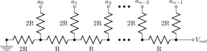
One thing the Pico doesn’t have is a digital to analog converter (DAC). In all the referenced cases and posts/videos, the experimenters used a circuit called a R-2R ladder, which consists of resistors in series/parallel, designed to convert digital 0s and 1s to voltages, and acts as a current divider. Balancing the resistors for smooth transitions and accuracy is time consuming, and you need a lot of resistors to choose from.
I decided to use the CA3338E D/A converter is lieu of the R-2R network constructed with discrete resistors. It is simple to use, and all the internal resistors on the die are balanced and matched. It comes in a 16-pin DIP handy for breadboard usage, can be used up to 50 MHz and responds well to the 3.3 volts from the Pico. Conveniently, all the digital inputs are on one side, except the D0 input. It has the standard TTL hookups, VDD on pin 16, and VSS on pin 8.
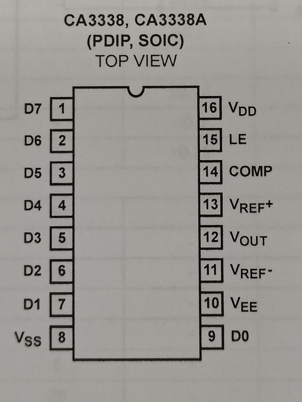
As my application is free-running, I grounded the latch enable (LE) pin 15. I also grounded the VREF- pin 11, COMP pin 14 and VEE pin 10. For more rigorous applications, I would have to use a clock into LE to reduce the glitch energy.1 I bypassed the VREF+ pin 13 to ground with 6.8 uF tantalum and 0.1 uF disk capacitors. Also, for testing purposes, I placed a series 82 \(\Omega\) and parallel 62 \(\Omega\) resistor across the output for the oscilloscope, giving ~1 volt P-P output.
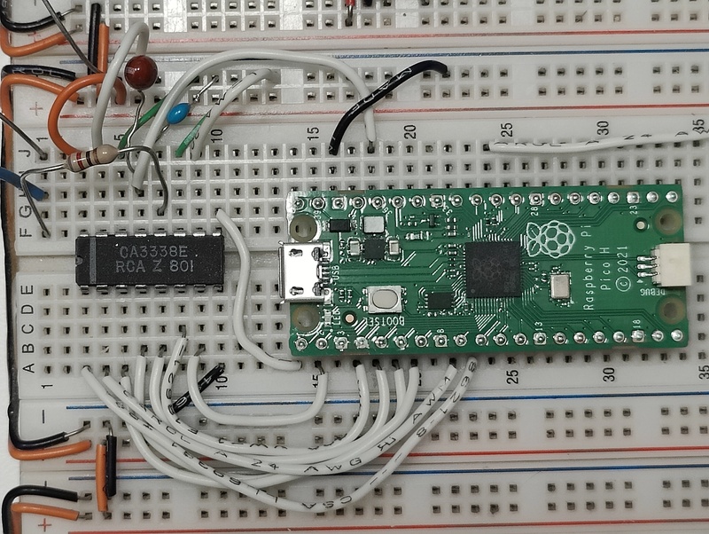
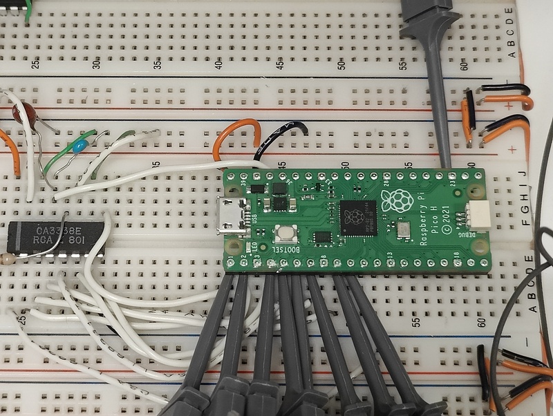
The Pico software is programmed to use GP0-GP7 for digital output. The software from Life with David, Episode 15 used pin group GP8-GP15, but as I intended to connect a OLED display and two variable resistors for analog to digital (ADC) input control, I changed it.
Well, that part didn’t work! The reason is I have not yet found a way to update the frequency and duty cycle on the fly, using the two variable resistors. Using a while() loop to reprogram the DMA hasn’t been successful. I suspect the DMAs panic when attempting to restart. More information is needed to deduce the problem. The short-term fix is install a RESET switch on the Pico, as when first power-up or reset, the DMAs and PIO are set up successfully. However, the second time is when the program barfs. As the frequency, waveform type and duty cycle are currently entered via the USB connection to the minicom terminal, this workaround works fine for now, even though it is a kludge.
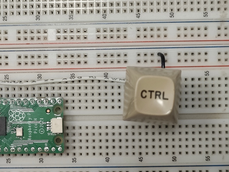
The momentary-contact RESET switch (labeled CTRL) connects from the RUN pin 30 of the Pico to ground. Another advantage to this is normal program loading requires the USB cable be removed, then while pressing the BOOTSEL button, replugging in the cable. With the RESET button, program loading consists of holding the RESET, then the BOOTSEL, releasing the RESET, then the BOOTSEL. That takes longer to describe than perform.
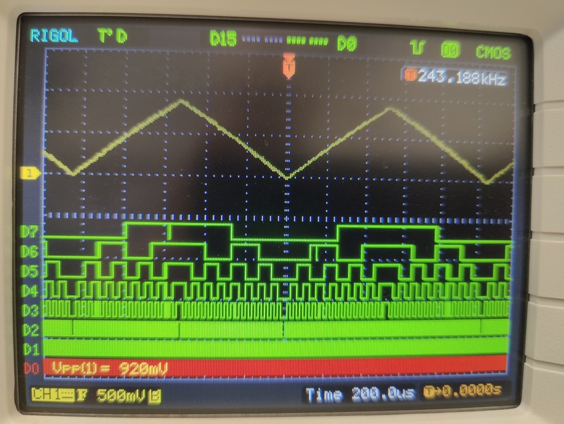
So, for example, entering a sawtooth wave for output, and a particular frequency, the above waveform is generated, and the digital inputs to the CA3338E ADC are shown. The frequency shown above is not the wave frequency, but the trigger frequency (currently on D0). The P-P wave is just under 1 volt into the oscilloscope.
I recommend the video, Life with David, Episode 15, as he does a masterful job of explaining each step of the base program. I don’t intend to duplicate that here.
Have a great day and may God watch over you and yours. Stay safe.
Footnotes
Non-clocked operation or changing data while LE is low is not recommended for applications requiring low output “glitch.”↩︎