Today I am talking about Pulse Width Modulation (PWM) on the Raspberry Pico. The Pico is such a nice little microcontroller to play with; but, like anything, it takes a while to figure out the idiosyncrasies of the language. Fortunately, the SDK book gives some idea of the statements available for the Pico, and consequently, the Pimoroni Tiny2040 which uses the same chip, the RP2040 microcontroller. Sometimes it is a bit of a challenge to determine which function comes out on which GPIO1 pin of the Tiny2040, as the number of available pins are different. The Pico PWM block has eight identical slices, each of which can drive two PWM output signals, or measure the frequency or duty cycle of an input signal. That gives 16 controllable PWM outputs which can be output on any of the 30 GPIO pins. The free-running counter that drives the PWM slices defaults to 125 MHz. So, the reciprocal of that gives a minimum pulse width of 8ns (nanoSeconds), or \(PW = \frac{1}{125e6} = 0.000000008\), which means the counter is stepped every 8ns.
Setting a wrap value determines the point where the counter resets back to zero (except for the phase-correct mode)2. For example, if you wished a period of ~768 ns, you could use pwm_set_wrap(slice_num, 96) which sets the slice’s counter reset for that time. Then if you wanted a positive pulse width of ~384 ns, you could use pwm_set_chan_level(slice_num, 0, 96). The zero is the channel, and the 96 is the number of 8ns pulses. For each PWM slice there are two channels available, A and B (or 0 and 1).
Several things have to be done to set up a particular slice for PWM output. First, tell which GPIO is allocated to the PWM with gpio_set_function(0, 4), where 0 is the slice and 4 is the GPIO’s selected function. The Raspberry Pico SDK manual lists the available functions in the section 4.1.10. hardware_gpio. Find which PWM slice is connected to which GPIO pin with uint slice_num = pwm_gpio_to_slice_num(0). Slice 0 is connected to GP0 (channel A) and GP1 (channel B). Then set the wrap point and positive pulse width as noted above.
After these commands are done the last step is to set the PWM running with pwm_set_enabled(slice_num, true). the variable slice_num was determined from the previous paragraph. If you wished to turn on several slices at once, you could use pwm_set_mask_enabled (69). The mask represents the eight PWM slices as the first eight bits. So, the 69 example above would be slices 0, 2 and 6 for bit mask 01000101.
Several new entries are added to the CMakeLists.txt file and the pwm.c files. For CMakeLists.txt, add target_link_libraries(pwm pico_stdlib hardware_gpio hardware_pwm) for the GPIO and PWM libraries. For the pwm.c file, add #include “hardware/pwm.h” to the top of the file. At this point, after doing the cmake .. from the build directory, and executing the make command, you just load the pwm.uf2 file onto the Pico (set as a flash drive per an earlier post).
One other thing I have done in the program below is have the clock signal (divided by 12) come out on pin GP21 just for fun. This requires adding #include “hardware/clocks.h” to the pwm.c file.
Code
// Output PWM signals on :// slice 0, pin 0// slice 2, pin 4// slice 6, pin 28// and a clock on pin 27.#include "pico/stdlib.h"#include "hardware/pwm.h"#include "hardware/clocks.h"int main(void) {// Basic CLOCK =125 MHz//GP21 ((CLK/12~10.5MHz) physical pin 27clock_gpio_init(21, CLOCKS_CLK_REF_CTRL_SRC_VALUE_ROSC_CLKSRC_PH, 12);// Tell GPIO 0 and 1 they are allocated to the PWM, function4gpio_set_function(0, 4); //PWM0(a)gpio_set_function(4, 4); //PWM2(a)gpio_set_function(28, 4); //PWM6(a)// Find out which PWM slice is connected to GPIO x uint slice_num0 =pwm_gpio_to_slice_num(0); // GP0 is PWM0(channel a) uint slice_num2 =pwm_gpio_to_slice_num(4); // GP4 is PWM2(channel a) uint slice_num6 =pwm_gpio_to_slice_num(28); // GP28 is PWM6(channel a)// The default clock is 125MHz and the divider is initialized to 1, // which means the counter is stepped every 8ns// Set period (wrap value)(cycles)pwm_set_wrap(slice_num0, 96); //768 nspwm_set_wrap(slice_num2, 48); //384 nspwm_set_wrap(slice_num6, 24); //192 ns// Set channel A(0) or B(1) output high for x cycles before dropping// Total pulse is cycles x 8ns (ex.:10cycles =80ns)pwm_set_chan_level(slice_num0, 0, 48); //0 is channel Apwm_set_chan_level(slice_num2, 0, 24);pwm_set_chan_level(slice_num6, 0, 12);// Note we could also use pwm_set_gpio_level(gpio, x) which looks up the// correct slice and channel for a given GPIO.// Set the PWM running//pwm_set_enabled(slice_num0, true);//pwm_set_enabled(slice_num2, true);//pwm_set_enabled(slice_num6, true);//There are times when you need to turn multiple PWM signals on or off and for this you can use:pwm_set_mask_enabled (69); //0,2,6on (bit mask 01000101)//The mask represents the eight PWM slices as the first eight bits.}
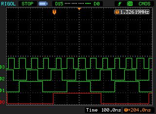
What does that look like. This image shows the outputs from the above program. D0: PWM0, D1: PWM2, D2: PWM6, D3: clock.
PWM outputs.
Notice the scope’s digital input is set for CMOS. The Pico runs on and outputs 3.3 volt logic level signals. Another post may explore a logic level signal converter I am thinking about, using a 2N7000 MOSFET. More on this later. This image is taken with the scope stopped, as there is a lot of jitter in the signals as they are not exactly synced. That is why the clock signal (D3) pulses seem of different widths.
That’s it for this post. Feel free to change and explore PWM. There are lots of things to do with it. More in another post, perhaps. Have a great day in the Lord Jesus, and stay safe!