Code
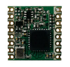
set(PICO_BOARD pico2)I am starting a new adventure, with long range (LoRa) transceivers,part of what’s called Internet of Things (IoT). The concept I am using is a peer-to-peer (P2P) setup, not part of LoRaWAN (wide area network). Specifically this effort is with the HopeRF Low Power Long Range Transceiver Module, Model No.: RFM95W, mounted on the breakout board from AdaFruit. CAUTION: Never start the module without a dummy load or antenna attached. Doing so could damage the module.
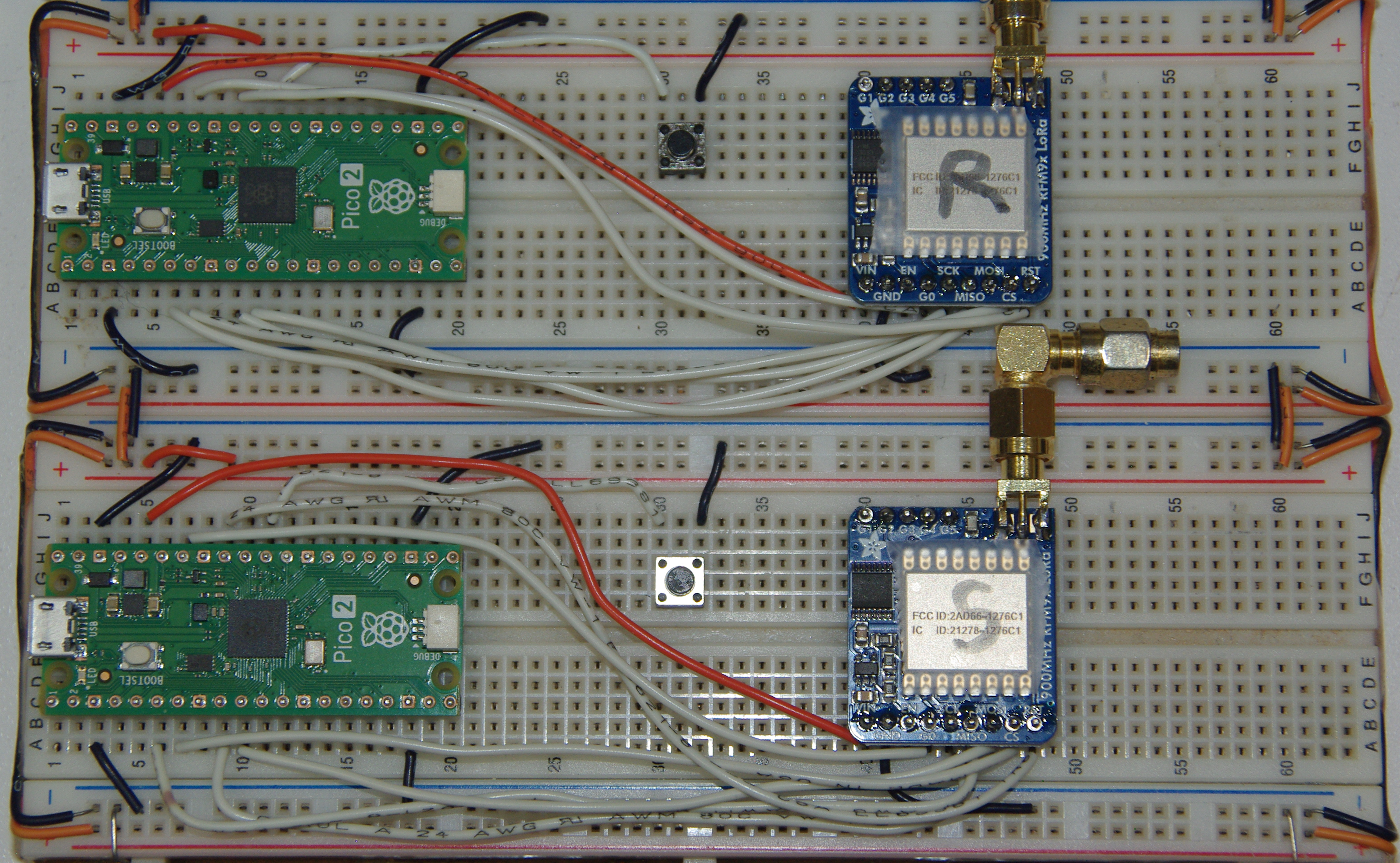
The above image shows two Pico2 microcontrollers and two LoRa modules, one as the sender (client) and one as the receiver (server), with two 50 \(\Omega\) dummy loads. Notice the reset buttons between each setup, the one thing it would be handy to have on any Pico board, as plugging and unplugging the USB connector damages it eventually.
An antenna for a 1/4 \(\lambda\) would be about 3.22 inches long. Straight wires could be used, but are not very efficient. I solder a SMA1 jack to the pads to attach a real antenna. Soldering four wires bent down at about a 45o angle to a BNC2 jack ground, and a wire to the center connector makes a great antenna, and is cheap to make. Using a SMA male to BNC male cable completes the connection. Do not use RP-SMA3 connectors as used for WiFi, on drones or first person view (FPV) goggles, as they are incompatible with standard SMA connectors. One potential module damaging bug hard to find is using a SMA jack with a RP-SMA plug, which is an open connection.
It is very similar to the RFM69HCW Packet Transceiver in many respects, that I’ve posted about in the past. In fact, I’ve found many of the library functions for the RFM69 will work with the RFM95. However, I’m finding there are a few caveats to keep in mind that can throw a monkey wrench in the works for the unwary.
I must mention that the first hurdle I ran into is the fact that, unlike the RFM96HCW project, I am using the newer Pico2 chip instead of the Pico. So, the PICO-SDK for Pico2 requires a bit different setup for the cmake and make to successfully compile the C++ code. In the CMakeLists.txt file, I had to add at the top:
set(PICO_BOARD pico2)The options are pico2, pico_w and pico. Also this assumes you use the latest PICO-SDK, which includes the latest board definitions. The original Pico uses the RP2040 processor, but the Pico2 uses the newer RP2350 processor, which doubles the RAM to 520 kB and 4 MB external flash, plus 24 PWM channels and 12 state machines.
One area the RFM95 is different is the register layout. When in FSK/OOK4 mode, different registers are used, although for LoRa mode, some of the FSK/OOK registers can be accessed. For LoRa mode, specific registers perform different functions/definitions, because the LoRa Modem can use spread spectrum transmission and forward error correction techniques, which allows reception of signals below the noise floor of the receiver.
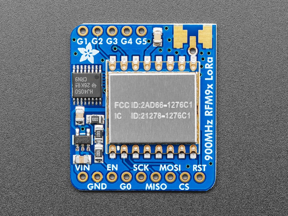
Manual reset is another area where the procedure is reversed from the RFM69. For the RFM95, pin 7 (NReset) of the module is pulled low for 100 uS, then released. After 5mS, the chip is ready for use. NReset is labeled RST in the breakout board image above.
static inline void manual_reset() { // RFM95W Datasheet, Ver 2.0, p. 111
  asm volatile("nop \n nop \n nop");
  gpio_put(RESET_PIN, 0); // set low
  sleep_us(100); // keep low for 100 uS
  gpio_put(RESET_PIN, 1); // set high
  sleep_ms(5); // chip ready after 5 mS
}
For the serial peripheral interface (SPI), the RFM95 requires the CS/NSS5 going low. Main in, subnode out (MISO) is high impedance when CS is high. For now, I am only using the DIO0 pin (labeled G0 on the breakout board). This provides interrupt signals for TXdone, RXdone and CADdone6. Because the use of a spread spectrum modulation technique presents challenges in determining whether the channel is already in use by a signal that may be below the noise floor of the receiver, CAD is used to detect the presence of other LoRa signals.
The actual packet structure is similar to the RFM69’s packet structure, but for LoRa, there are differences. For example, a packet starts with a default 12 symbol long preamble; and for explicit mode, adds a header and CRC, then the payload, followed by an optional payload CRC.
The carrier frequency I am using is 915 MHz7. The module has a range (high range) of 862 - 1020 MHz. This is the same range I am using for the RFM69HCW mentioned earlier. Setting the desired frequency is pretty straightforward. The carrier frequency is set using the three frf registers (MSB, MID, LSB), for a 24-bit value:
\[F_{RF} = F_{STEP} \times frf(23,0)\]
The FSTEP is defined as:
\[F_{STEP} = \frac{F_{XOSC}}{2^{19}}\]
As the module’s crystal oscillator frequency is 32 MHz, and the frequency synthesizer step (FSTEP) is 61.0 Hz, the module can be set almost anywhere within that range mentioned above. So, to determine the frf values:
\[frf = \frac{915000000}{61.03515625} = 14991360\]
These hex values (0xE4, 0xC0, 0x00) are placed in the three registers (0x06, 0x07, 0x08 as follows:
write_register(RegFrfMsb, 0xe4);
write_register(RegFrfMid, 0xc0);
write_register(RegFrfLsb, 0x00);
The function for write_register is shown below, and can be used for any register:
static void write_register(uint8_t reg, uint8_t data) {
  uint8_t buf[2];
  buf[0] = reg |= WRITE_BIT; // wnr bit8 to 1 for write access
  buf[1] = data;
  cs_select(); // active low
  spi_write_blocking(spi0, buf, 2);
  cs_deselect(); // set high
  sleep_ms(10);
}
Notice I am using the Pico2’s spi0 pins. Also, WRITE_BIT (0x80) is defined in the header file. So far, I have been able to access the registers, set the frequency, build a packet message and place it into the FIFO register. I have yet to transmit a message, or receive a message, but that will be in future posts. I have proven that the modules work by using microPython code in two modules (one Client, one Server) successfully. Now I am still converting that and RadioHead’s library from Arduino code to C++ code, as I don’t have any Arduinos.
So, until next time, God Bless you and yours. If you don’t know God, and His Son Jesus, don’t wait too long, as we are in the Last Days!
SubMiniature version A (SMA) connectors are most commonly used in microwave systems, hand-held radios, mobile telephone antennas and WiFi antenna systems.↩︎
BNC means Bayonet Neill–Concelman and is a miniature quick-connect/disconnect radio-frequency connector for coaxial cable.↩︎
Reverse-polarity SMA connectors are used on WiFi and are designed to prevent consumers from connecting antennas that provide additional gain and therefore breach Part 15 compliance.↩︎
FSK is frequency shift keying, and OOK is on-off keying.↩︎
NSS stands for negative slave select, meaning selected when active low.↩︎
CAD stands for channel activity detection.↩︎
The Industrial, Scientific, Medical band is for low power devices primarily used for experimentation purposes. See this link for more detail.↩︎