Casual Microstrip Design 4
Following Casual Microstrip Design 3, I wanted to explore the differences when using the modified formulas that include the third dimension of a microstrip, the thickness of the conductor. These two formulae are similar, but the value to find is effective strip width ratio, We/h.
For W/h (/2 ), [\[\begin{equation}
\frac{W_e}{h} = \frac{W}{h} + \frac{t}{\pi h} \left(1 + ln \frac{2 h}{t}\right)
\end{equation}\]] For W/h (/2 ), [\[\begin{equation}
\frac{W_e}{h} = \frac{W}{h} + \frac{t}{\pi h} \left(1 + ln \frac{4 \pi W}{t}\right)
\end{equation}\]] Some restrictions apply to the above formulas: (t h : and : t W/2). Typical strip thickenss varies from 0.0002 to 0.0005 inch (5.1 um to 12.7 um) for metalized alumina substrate, and from 0.001 to 0.003 inch (25 um to 76 um)1 for low-dielectric substrates.
For an example, let’s use the chart from Casual Microstrip Design 3, but show the difference when using the conductor thickness. We will use the same substrate values: er = 9.8, h= 1.6, but adding the conductor thickness, t=35 um and an impedance range of (50 Z_o ) for better definition.
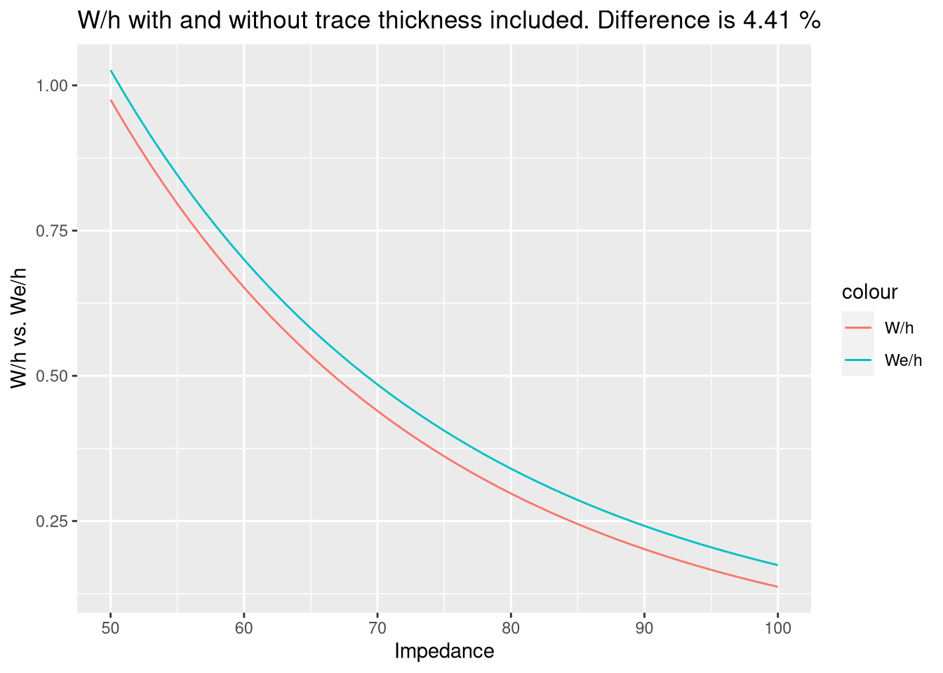
Using these formulas, the above chart shows there is negligible difference between W/h and We/h. The overall difference, using the mean values, is shown in the chart title. However, this could be significant, especially if impedance matching is critical, or at higher frequencies.
Hopefully, the next posts in this vein, will be on laying out some real circuits. Until next time, stay safe and God Bless!
-
The average thickness for 1 oz copper traces is 35 um.↩︎