Workflow for ElmerFEM
As part of my exploration of modeling a microstrip over substrate, I have jumped headfirst into the unknown (to me) world of simulation.
I first tried FDTD1 but my attempts in installing and using OpenEMS2 have not coalesced into a working environment.
Then I stumbled upon ElmerFEM3, a set of tools to simulate FEM4. From the Elmer Overview, it is described as follows:
Elmer is a finite element software package for the solution of partial differential equations. Elmer can deal with a great number of different equations, which may be coupled in a generic manner making Elmer a versatile tool for multiphysical simulations.
Sounds great, if I could make it all work with the existing modeling tools I already use. So that’s the purpose of this post, to define a workflow from start to finish. The tools I will use to accomplish that are the following:
- OpenSCAD5 export as .csg file.
- FreeCAD6 export as .brep file.
- gmsh7 export as .msh file.
- ElmerGUI saves a .vtu file.
- ParaView8 inputs the .vtu file.
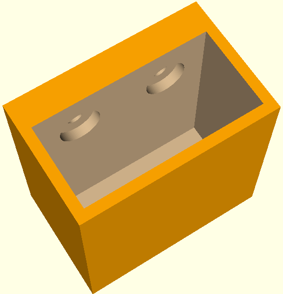
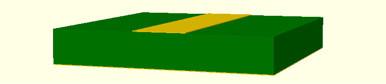
Firstly, I used OpenSCAD to design a 3D model9 as it uses simple text files, which allows precise control of dimensions for any project. After designing the project, I export as a ‘.csg’ file. This file then is opened in FreeCAD.
I have not used FreeCAD for any designs at this point, just as a converter in the chain. Perhaps later… After loading the file, I then export as a ‘.brep’ file, which is a compatible format for gmsh input. If I wish to change the mesh size, I can then run, from the CLI, the command: gmsh <filename.brep> -clscale 0.01. The scale can be what works for the particular design. If it’s too blocky, or circles are not correct, then I could use a smaller mesh. However, a smaller mesh will take longer to render.
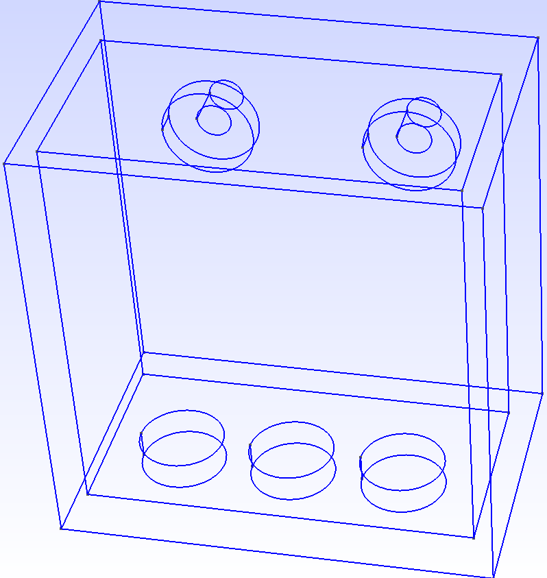
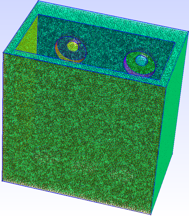
Upon first loading, an outline is shown. After the meshing operation, the file is saved as a ‘.msh’ file. This file is now ready to be imported into ElmerGUI.
I am using ElmerGUI as the interface as it is fairly straightforward. However, setting required parameters is a totally different experience. Fortunately, documentation is available, and with a little bit (lots) of reading, models can be selected to perform the desired calculations. I won’t go into much details, as this post would be 20 pages long. Suffice it to say, under the Model section, menus are selected for equations, materials, body force, initial and boundary conditions for the simulation. Next step is generating a solver input file, using the ‘Sif’ menu option. Once the solver is run and assuming convergence10 is successful, the project is saved as a ‘.vtu’ file. The next function is viewing the results in ParaView.
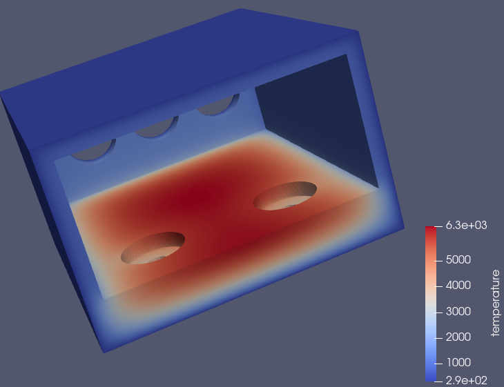
This particular simulation is a simple heat distribution equation starting from room temperature (293oK/68oF). The scale shown on the lower right may be off, as 6300oK seems a bit warm. That’s 10,800oF. So I think some value is wrong in this example…
Anyway, after I get more familiar with all the pieces of the process, I will do better, Lord Willing! So, the next step is design a working model of a microstrip on substrate for electrostatic explorations. Till next time, God Bless. Time is getting short for the Lord’s return. Pray you are right with Him before it’s too late.
Footnotes
Finite-difference time-domain (FDTD) is a numerical analysis technique used for modeling computational electrodynamics (finding approximate solutions to the associated system of differential equations). Since it is a time-domain method, FDTD solutions can cover a wide frequency range with a single simulation run, and treat nonlinear material properties in a natural way.↩︎
OpenEMS web pages: https://www.openems.de/ are currently broken, so it’s difficult to find documentation and examples.↩︎
Elmer web pages: https://www.csc.fi/elmer.↩︎
The finite element method (FEM) is a popular method for numerically solving differential equations arising in engineering and mathematical modeling.↩︎
OpenSCAD does not focus on the artistic aspects of 3D modelling, but instead focuses on the CAD aspects. Website: https://openscad.org.↩︎
FreeCAD is a free, open-source parametric 3D modeling application. It is made primarily to model real-world objects, ranging from the small electronic components up to buildings and civil engineering projects, with a strong focus on 3D-printable objects. Website: https://github.com/FreeCAD/FreeCAD/releases.↩︎
Gmsh is a three-dimensional finite element mesh generator with a build-in CAD engine and post-processor. Its design goal is to provide a fast, light and user-friendly meshing tool with parametric input and flexible visualization capabilities.↩︎
ParaView is an open-source application for visualizing two- and three- dimensional data sets.↩︎
This particular model is a holder I placed on my tractor to hold a Byrna launcher↩︎
If convergence is an issue because of non-connected parts, try from the CLI: ElmerGrid 14 2 <file.msh> -merge 1.e-6.↩︎