Recently I managed to find some understandable libraries for the Raspberry Pico to drive an Organic Light Emitting Diode (OLED) display and environmental sensor. This has allowed me to progress with my latest little project: Have a OLED display show the current temperature, humidity and barometric pressure of the surroundings. “What’s so hard about that,” you ask. Well, I am just beginning experimentation using the Pico microcontroller for other projects. And, to add more fun, interface that with the Bosch BME280 Sensor module, and a OLED display. Additionally, although I have successfully interfaced the sensor with the Pico, it was using Serial Peripheral Interface (SPI) protocol instead of Inter-Integrated Circuit (I2C) protocol. I wanted to use i2c for two reasons. Firstly, I had not used i2c for much except on the Raspberry Pi 4 for a real-time clock (RTC). Secondly, I wanted to get my feet wet with the STEMMA QT connector system.
I2C vs. SPI
The most apparent difference between i2c and SPI is that i2c works as a 2-wire bus, needing only serial data (SDA) and serial clock (SCK) lines for data transmission and synchronization. SPI, on the other hand, requires four wires to control a single slave: slave clock (SCK), master out slave in (MOSI), master in slave out (MISO), and slave select (SS).
SPI’s advantages make it appropriate for applications like reading/writing data to an SD card, or any other application where data transfer speed is essential. Conversely, i2c tends to be strong when sending rather simple control signals to multiple peripherals, such as reading from a real-time clock or adjusting the volume of a remote speaker. Users can also utilize SPI for remote speaker control, though SPI’s more complex wiring requirements may make it a less attractive option. As a very simplified rule of thumb, you might say that SPI is a better choice for the small number of peripherals that need to transfer a large amount of data. I2C is the best option if you need to control many peripherals, especially if you are transferring a small amount of data to each one. Your application, of course, may be different, and designers should also consider what devices are available that support only one protocol or the other.
For easy connection of multiple modules, I decided to use STEMMA QT (‘cutie’) / Qwiic connectors, otherwise known as 4-pin JST PH connectors, with a 1.0mm pitch connector pin spacing, which are easier to fit on a small sensor board, where the larger JST PH 2.0mm pitch won’t fit. The larger cables are compatible with Grove and Gravity boards, where the smaller QT are compatible with Sparkfun’s Qwiic boards.
The Project
Seems I tried way too many library versions to find a driver that wasn’t overly complicated, and would satisfy my desire to simply acquire sensor date and then send it to the OLED display. Some libraries (Bosch) were extremely obtuse, where others (Arduino) were only applicable to Arduino boards and associated libraries. However, I had some hopes for attempting to use Arduino-compatible layers, but that didn’t work either, as it always wanted me to download just one more library to get it working. Finally, I scrapped all those libraries when I ran across a nice simple, straightforward set of libraries by Takuya Otani at https://github.com/ta98otani/RPi-Pico-BME280_SSD1306 and OLED driver files at https://github.com/mbober1/RPi-Pico-SSD1306-library. The OLEDs I have all use the SSD1306 chip to control the display, whether it is a 128x32 or 128x64 size. The included ‘README.md’ file explains all the details, and assumes you have the Pico C/C++ SDK environment installed on the Raspberry Pi (or other computer).
The Hardware
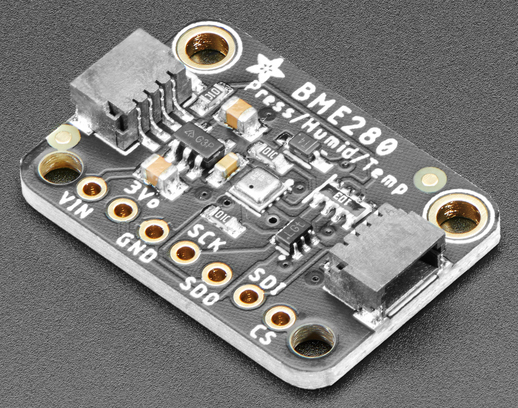
The Bosch BME280 Sensor that I selected from AdaFruit.com reads temperature, humidity and barometric pressure, in a package the size of a postage stamp. Even smaller is the sensor itself, the tiny silver-colored device in the center of the board below. The breakout board can be addressed via SPI or i2c. The SPI signals are connected via header pins that can be soldered to the board (handy for a breadboard). The i2c signals can be connected to the same pins, or to the STEMMA QT jacks (of which the board has two, one on each side). The sensor can be daisy-chained with other sensors; or in my case, to the OLED display.
BME280 Sensor.
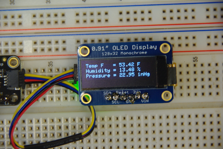
The OLED 128x32 display also from AdaFruit.com, has holes for header pins for breadboard use; or, unseen on the back, a STEMMA QT jack for daisy-chaining as mentioned above. However, it only has one jack, so has to be at the end of the other boards. By using the header pins, it can be connected anywhere.
The Connections
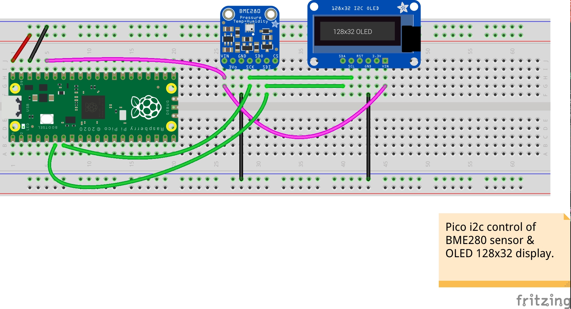
The below image shows all the connections for the Pico, sensor and display. I am using a newer sensor than depicted below, but an image is not available yet in the AdaFruit library for Fritzing. The red and black wires are 5V power and ground respectively. The pink wires supply the 3.3V to power both boards. The green wires are the clock (SCK/SCL) and data (SDI/SDA) signals from the Pico. Each sub-board can supply 3.3V to other circuits, but is not used here. Each board is addressed individually, using the i2c default address for that particular board. The address can be found using a i2c bus scanner program, or found in the documentation for that board. For example the BME280 board can have two addresses, depending on the state of the SDO pin. If it is high, the address is 0x77, if low is 0x76.
I did two versions to depict the wiring possibilities, one with the STEMMA QT/Qwiic cables, the other with discrete wire jumpers.
QT Board.
Notice I am using a Pimoroni Tiny2040 board instead of the Pico. However the same software works for both, only the pinout is different.
Wired Board.
If you wished to solder the components into a perfboard, this would the route to take, and save the cables for another project, unless you wished to mount the sensor remotely.
The Libraries
During compilation, I was getting missing file errors, so had to move the GFX.hpp, logo.hpp, and SSD1306.hpp libraries from their sub-directories to the main directory. That was using the included CMakeLists.txt file as-is. The *.cpp files I was able to leave in their separate sub-directories. The logo.hpp file is not really necessary, and in the original, is not seen as it goes by too quickly. I think it is cute, so I added a 1-second delay so it shows.
The Software
For my application, I had to change a few things in the libraries. In the BME280_read.cpp file, I changed the i2c1 references to i2c0, and the GP14 and GP15 references to use GP4 and GP5. Also the Tiny2040 board has less pins, and the GP14/GP15 pins are not available.
After moving some *.hpp files as mentioned in the “Libraries” paragraph above, I also changed the BME280_read.cpp include statements from #include <library> to #include “library” for those particular files.
I also wanted to display temperature in Fahrenheit instead of Celsius, and the barometric pressure in inches of Mercury (inHg) instead of Pascals (hPa). So I modified the temperature calculation from temperature/100.0 to temperature/32.55555556. It is non-intuitive, but if the Celsius is used without dividing by 100.0, the display will read 0.00C.
Barometric pressure conversion changes slightly depending on temperature. For example, if the temperature is 15.6oC (60oF) or higher, the conversion is pressure/3376.85; if around 0oC (32oF), the conversion is pressure/3386.38. However, having said that, I notice the latest version I have of Lide (2007), the variables are removed1 and only 3386.38 is used. In any case, the difference is probably not significant for casual usage. So, below is what I am using, right or wrong. I may delete it in the future for simplicity.
The sprintf() function concatenates the variables into a string, stored in the first variable. The C++ function cout could conceivably be used instead, but I did not experiment with that, as I was just happy to finally get something to work! Perhaps I will try that in the future. Perhaps it would look something like this: variable = cout << “Text” << data;
The OLED can display four lines and still be readable, as this block shows.
Code
oled.drawString(0,0, tempChar);oled.drawString(0,8, tempF);oled.drawString(0,16, humidityChar);oled.drawString(0,24, pressureChar);oled.display(); //Send buffer to the screen
However, it does make for a busy display. The below code block uses only three lines, and displays the temperature in Fahrenheit, as I prefer.
Code
oled.drawString(0,0, tempF);oled.drawString(0,10, humidityChar);oled.drawString(0,20, pressureChar);oled.display(); //Send buffer to the screen
I only show the parts I modified, not all the files. Those can be downloaded as mentioned previously in the Project paragraph.
The Results
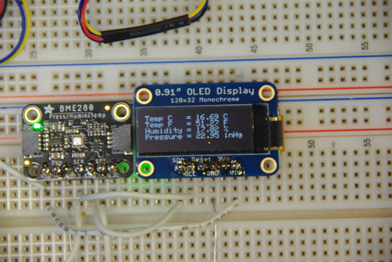
Here is the display showing all four lines, with the temperature showing both Fahrenheit and Celsius. As mentioned earlier, it is a bit busy.
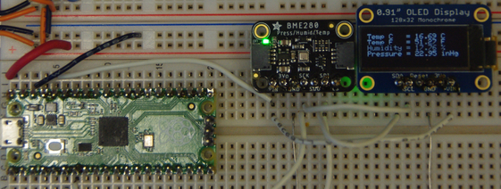
This next image shows only three lines, making it slightly easier to read, especially from a distance, or for older eyes, like mine!
The character set (font) used in these libraries is an 8x5 layout. As each character is eight pixels high, and the display is 32 pixels, four lines uses everything! As you can see, three lines gives better separation.
The Future
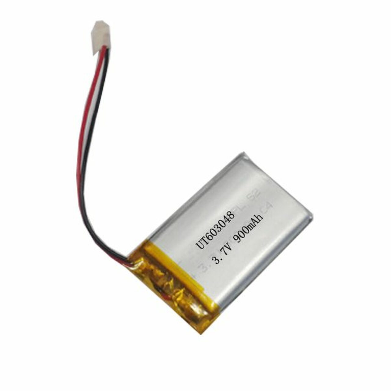
One interesting module I found online was a small board called a LiPo Shim from PiShop.us that can be soldered on the underside of the Pico headers, and adds a power switch and a jack for a 3.7V Lithium Polymer (LiPo) battery to allow for self-contained power. Also, by holding the Pico’s BOOTSEL button and toggling the power switch, the Pico could be placed in Mass Storage mode without removing and reconnecting the USB cable for file loading.2
By using a 1/2 size protoboard, which fits nicely into a normal-sized Altoids can, and mounting the three modules on it, a nice portable weather station is created. That’s what I am thinking about as the culmination of this project. Other uses are just waiting to be discovered. One more possible option is a 128x64 display. This will allow each line to be double size, or 10x16 character size. No reading glasses needed!
We thank God for all that we have, including the very breath we breathe. If you don’t know God, there is no time like the present to ask God for forgiveness through His Son, Jesus Christ! God Bless you and yours, and stay safe.