#include "hardware/gpio.h"
#include "hardware/adc.h"
#include <stdio.h>
#include "pico/stdlib.h"
#include "hardware/i2c.h"
#include "logo.hpp"
#include "GFX.hpp"
#include "SSD1306.hpp"
#include "font.hpp"

int main() {
  adc_init();
  //stdio_init_all(); // for possible output to minicom
  sleep_ms(1000); // delay  to allow display to catch up to MPU/CPU
  // Make sure GPIO is high-impedance, no pullups, etc. for ADC
  // Select ADC inputs 0 (GPIO26)
  adc_gpio_init(26); // input from hall effect sensor, pin 31
  // This example will use i2c0, and GP4 and GP5 on pico and Tiny2040
  i2c_init(i2c0, 400 * 1000);
  gpio_set_function(4, GPIO_FUNC_I2C); // SDA
  gpio_set_function(5, GPIO_FUNC_I2C); // SCL
  gpio_pull_up(4);
  gpio_pull_up(5);
  // OLED address 0x3D for 128x64, 0x3C for 128x32
  GFX oled(0x3C, size::W128xH32, i2c0);   //Declare oled instance
  oled.display(logo);                     //Display pico bitmap
  sleep_ms(1000);                         //  for 1 second
  char title[32]; // string for title
  char duty[32]; // string for tesla reading
  char gauss[32]; // string for gauss reading
  char data[32]; // Praise God!
  while (1) {
      adc_select_input(0); // for hall effect value
      uint16_t result = adc_read(); // get setting
      int dutyC = result /10.7763; // convert voltage to range 380 max.
      int gaussC = dutyC * 10; // convert milliTeslas to Gauss
      sprintf(title, "Magnetic Flux Density"); // title
      sprintf(duty, " Level = %4d mTesla",   dutyC); // milliTesla
      sprintf(gauss, " Level = %5d Gauss", gaussC); // Gauss = mT * 10k
      sprintf(data, "-Praise God for All-"); // text
      oled.clear();
      oled.drawString(0,0, title); // buffer entries and locations
      oled.drawString(0,8, duty);
      oled.drawString(0,16, gauss);
      oled.drawString(0,24, data);
      oled.display();                     //Send buffer to the screen
      sleep_ms(500);
  }
  return 0;
}Pico & Magnetic Fields
pico
electronics
Here we are again with another Pico adventure! This time we are exploring magnetic fields, and using the Pico to measure generated flux densities.
“How are you going to do that?” you ask. Well, we will generate a magnetic field using a device called a Helmholtz Coil. This is a device, simplistic in its approach, but sophisticated in results.
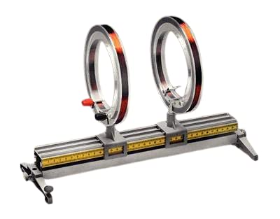
A Helmholtz pair consists of two identical circular magnetic coils that are placed symmetrically along a common axis, one on each side of the experimental area, and separated by a distance h equal to the radius R of the coil. Each coil carries an equal electric current in the same direction.
Setting h = R, which is what defines a Helmholtz pair, minimizes the non-uniformity of the field at the center of the coils, in the sense of setting \(∂^2 B / ∂ x^2 = 0\) (meaning that the first nonzero derivative is \(∂^4 B / ∂ x^4\) as explained below), but leaves about 7% variation in field strength between the center and the planes of the coils. A slightly larger value of h reduces the difference in field between the center and the planes of the coils, at the expense of worsening the field’s uniformity in the region near the center, as measured by \(∂^2 B / ∂ x^2\).
When a Helmholtz pair of coils carry an equal electric current in the opposite direction, they create a region of nearly uniform magnetic field gradient. This is known as anti-Helmholtz coil, and is used for creating magnetic traps for atomic physics experiments.
In some applications, a Helmholtz coil is used to cancel out the Earth’s magnetic field, producing a region with a magnetic field intensity much closer to zero.
Where we need to calculate the magnetic field intensity1, we can use the following formula, which gives the exact value of the magnetic field at the center point.
\[B = \left(\frac{4}{5}\right)^{3/2} \frac{\mu_o n I}{R}\]
where radius is R, n is number of turns in each coil, I is current, B is magnetic field and \(\mu_o\) is the permeability of free space, \(4 \pi \times 10^{-2}\) N A-2, or \(12.566370614 \times 10^{-2}\) N A-2 (newton amperes).
Now we need some method to measure/determine the field variations within and outside the apparatus. This is where the Pico comes in. However, before we can utilize the Pico, we need something to detect the field intensity itself. We can use a hall effect sensor to do that part. The part I settled on is the DRV5055A3 Ratiometric Linear Hall Effect Sensor in a TO92 package with three leads, VCC, GND and OUT. As the Pico uses 3.3 volts, I can use that output from the Pico to drive VCC. The DRV5055A3 has a sensitivity of about 15 mV/mT (0.015V/0.001T) for 3.3 volts. There exists digital sensors also, but as they are basically on/off sensors similar to a reed switch, they were not suitable for my use.
In the centimetre–gram–second (CGS) system, a smaller unit of the magnetic field (B-field) is Gauss, denoted by the symbol G. The relation between Tesla and Gauss is given as 1 T = 10,000G.2 For those who desire more information, Tesla (T) can also be defined as:
\[T=\frac{V.s}{m^{2}}=\frac{N}{A.m}=\frac{J}{A.m^{2}}=\frac{H.A}{m^{2}}=\frac{Wb}{m^{2}}=\frac{Kg}{C.s}=\frac{N.s}{C.m}=\frac{Kg}{A.s^{2}}\]
where, V = volt, s = second, m = meter, N = newton, A = ampere, J = joule, H = henry, Wb = weber, Kg = kilogram, and C = coulomb.
In this usage, I will use a 128x32 pixel organic light emitting diode (OLED) display, as I used in this post for a weather station. The OLED is a perfect size for this application, as I only need to display the field intensity, and this one has 4 lines available for a font size of 8x5, also shown in this post. The OLED uses I2C0 port SDA and SCL (GPIO 4 and 5), with 3V3 (pin 36).
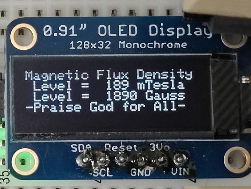
This is the simple readout I currently have for the circuit. The hall effect sensor feeds into the analog/digital converter (ADC0) on GPIO 26 (pin 31).
The short program to do all this is below.
For the above program to work, you need the OLED drivers and font from Takuya Otani, mailto:ta98otani@gmail.com. Also the SSD1306 library is needed. It can be retrieved into the project’s root directory as such: git clone https://github.com/mbober1/RPi-Pico-SSD1306-library.git. I also have a Reset switch (N/O) on RUN pin 30 to save wear and tear on the micro USB connector for program uploading.
Footnotes
Magnetic field intensity, measured in Teslas, is commonly referred to as the B-field, and refers to the force it puts forth on a moving charged particle. Consider the implications…↩︎
The CGS system has been largely supplanted by the MKS system based on the meter, kilogram, and second, which was in turn extended and replaced by the International System of Units (SI).↩︎