Continuing our adventure with the Raspberry Pico board, this post is about using the pulse width modulation (PWM) function to exercise a servo which may be used as a Radio Control (RC) part for a model airplane or drone, for example. We are having great fun finding uses that parallel our interests, one of which is RC control of drones.
In the past I have built several drones from scratch, one starting as a octocopter, then as a hexacopter and ending as a quadcopter. The different configurations were caused, as you can imagine, from crashing and breaking things! Drone frames are hard pressed to survive a crash from 20 meters in the air when a blade comes off, or the controller loses contact with the airframe, for example. Crunch!
But, this post is not to discuss any particular learning process and associated mishaps involved in operator error. This post concerns the Raspberry Pico (or Pimoroni Tiny2040) using one of its PWM slices to exercise a simple servo. Sort of a burn-in test of the servo before placing in an airframe. Failure is cheaper on the workbench than in the air at 500 feet!
This circuit I describe follows earlier posts on the Pico board, and furthers my learning of the Pico software development kit (SDK). Earlier I tried reusing similar C++ programs by varying the on/off time in a for() loop; but since the PWM accepts changes only after a wrap-around of the counter value, it was not working. Then, I stumbled upon a program using a interrupt handler function I was able to modify to my needs, and it worked! So, this is what the post will detail. I admit I am still working on understanding interrupts on the Pico, and still am learning.
Before I get into the actual C++ program, I have to set up the environment for the servo itself. Most servos work on 5V logic levels, not 3.3 volts. So, the first step is to detail the logic level converter I am using. I know level converter boards can be obtained from many retailers1 on the Internet, but as the circuit is fairly simple, I built my own using discrete parts. A well-stocked “Junk Box” is really a must if you tinker with electronics at all!
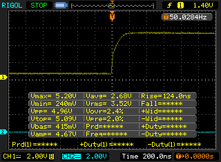
Parts count is very small for the converter circuit. Firstly, an inexpensive Enhancement-mode N-Channel MOSFET such as the 2N7000 fits the requirement. Adding two resistors, where the value can vary from 10k() to around 680() will work, depending on speed requirements. Both must be the same value, whatever you choose. I will use 680(); although at this low speed, 10k() would work as well. It really depends on how quickly you need the pulse to reach a positive logic level, which is directly related to the circuit capacitance. As seen below, the rise time to full level is ~124 nS. The current for the high side would about 7mV, added to the servo motor’s current requirement.
Rise time.
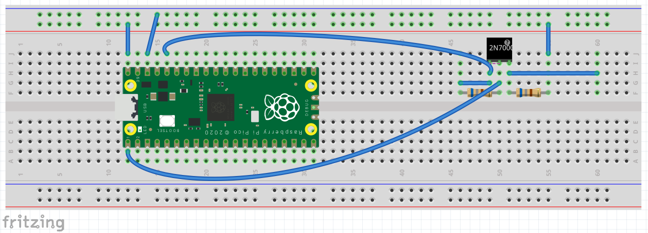
The logic level needed to trigger a positive pulse would be reached even before that. So if current draw is an issue, a higher resistance value would be better. A picture is worth 1000 words, so here is the Pico connected to the level converter. Click here to see the level converter circuit. The top blue wire is 3V3 for the low side power reference, the lower blue wire is the PWM signal, and the far right horizontal wire is the 5V high level output.
Pico and Level Converter.
Most servos want to see a signal with a period of 20mS, which is 50 Hz frequency. The duty cycle2 needed to position a servo varies from 1mS to 2mS, with 1.5mS considered the center or neutral point. The period is also known as the pulse repetition rate (PRR) if there is only one pulse during each period. Obviously, this would not apply to pulse position modulation (PPM) where there may be many discrete pulses during any period. As I’ve mentioned in earlier posts where we set up a particular PWM slice3 by telling the counter how far to count before wrapping, on what pin to place the output and what portion of the signal we want as high and low. Those steps are:
Set the GPIO pin we want for PWM output,
Determine which slice connects to the pin selected,
Set the counter wrap value (divider),
Set an interrupt to handle when the counter wraps,
Perform actions when the interrupt is triggered.
Most of the actions above we have performed in earlier posts on Pico PWM. However, the last two lines above are the meat of the program, so to speak. For me, that is new territory on the Pico. In past times, I have worked extensively with interrupts on the AVR series of microcontrollers, but the Pico SDK is totally new to me. Mostly what needs to be discovered are the names for the interrupts available. We don’t really want to use the interrupt numbers directly, as that reduces future upgrade ease, if numbers change or new interrupts are added. The Pico is fairly new, so that scenario is very likely!
Onward and upward! There is a file included in the Pico SDK, called irq.h that lists the names for the interrupts.4 The one we will use triggers on a counter wrap, and is IRQ #4, called PWM_IRQ_WRAP. In the main() portion of the program, we will set it up using the command, irq_set_exclusive_handler(PWM_IRQ_WRAP, on_pwm_wrap) to install a single handler for the interrupt. The second option on_pwm_wrap simply names the handler we create to handle the interrupt. To recap, we will clear the slice’s interrupt, set it up as shown above, then enable it.
The next step is create a function that will handle the interrupt when it occurs. As mentioned before, the interrupt triggers when the PWM counter hits the wrap value. What we have to do first is clear the interrupt. Since we want a variable positive pulse width, we have two count cycles, one going up and one going down. We use a if/else sequence for that, each which counts up (or down) one count for each interrupt. We already know the range of the pulse, so now we calculate the required divider value to achieve the min and max. The formula for that is, \(divider = \sqrt{\frac{dutycycle}{period } \times 255^{2}}\). For the minimum pulse width of 1 mS, the values are: period = 0.02, dutycycle = 0.001. For the max, the dutycycle = 0.0015.
The values derived in the above paragraph, 57 for the minimum and 81 for the maximum, are then used in the if/else loop. These values are counted up and down respectively and set using pwm_set_gpio_level(0, divider divider)* as the last step in the interrupt. Notice the divider value is squared to increase linearity. The zero is the slice number used. You could also change it to slice_num as it is in the main() function. I have not tested it to see if it works as a local variable or global variable in the function.
Warning:, first set the divider value in the handler to start with the minimum pulse width. If it is started at 0, it may cause the servo to exceed its mechanical limits and stick, thereby causing excessive current draw and eventual motor burnout.
Here is the complete program for the servo exerciser.
Code
/* Servo exerciser. 50Hz (20ms period) with 1ms to 2ms duty cycle. Output on GP0. Use level converter (3v3 to 5v)for more reliable servo action. */#include "pico/stdlib.h"#include <stdio.h>#include "hardware/irq.h"#include "hardware/pwm.h"void on_pwm_wrap(); //function to handle interrupt.int main() {// Set the GPx pin for PWM functiongpio_set_function(0, GPIO_FUNC_PWM);// Figure out which slice we just connected to the output pin uint slice_num =pwm_gpio_to_slice_num(0);// Mask our slice's IRQ output into the PWM block's single interrupt line,// and register our interrupt handler.pwm_clear_irq(slice_num);pwm_set_irq_enabled(slice_num, true);irq_set_exclusive_handler(PWM_IRQ_WRAP, on_pwm_wrap);irq_set_enabled(PWM_IRQ_WRAP, true);// Get some sensible defaults for the slice configuration. By default, the// counter is allowed to wrap over its maximum range (0 to 2**16-1). pwm_config config =pwm_get_default_config();// Set divider, reduce counter clock with divider value.// divider = clock /65536/ freqpwm_config_set_clkdiv(&config, 38.15f);// Load the configuration into our PWM slice, and set it running.pwm_init(slice_num, &config, true);// Everything after this point happens in the PWM interrupt handler,// so we can loop forever.while (1)tight_loop_contents();}void on_pwm_wrap() {// divider =sqrt([dutycycle/period]*255^2) static int divider =57; // set to 1ms to not over-torque servo on startup. static bool going_up = true;// Clear the interrupt flag that brought us here.pwm_clear_irq(pwm_gpio_to_slice_num(0));if (going_up) {++divider;if (divider > 81) { //sqrt([dutycycle/period]*255^2) divider =81; going_up = false; } } else {--divider;if (divider < 57) { //sqrt([dutycycle/period]*255^2) divider =57; going_up = true; } }// Square the divider value to make more linear.pwm_set_gpio_level(0, divider * divider);}
Well, this post is long enough, so that’s it! Look to God if you need answers, and accept His Son Jesus as your Lord and Savior. Have a great day, and stay safe!
Footnotes
Small volume retailers such as Sparkfun.com carry most needed parts.↩︎
Duty cycle is defined as a signal’s positive pulse width.↩︎
There are eight PWM slices available on the Pico.↩︎
The Pico SDK PDF file also lists the names in the hardware_irq section.↩︎