Atmega 168/328 Microcontroller
Today I decided to install the AVR toolchain onto the Raspberry Pi-4. Pretty simple process using ‘APT’ to install the ‘GCC AVR’ libraries. I also installed ‘AVRDUDE’ to access the Atmega 168/328 chips, or any other Atmega chip for that matter. But, this post is not about installing the required software on the PC.
Some folks are inclined to install the Arduino IDE (Integrated Development Environment) as a way to access the Atemga line of chips, especially if they have or wish to use a ‘NANO’ board of some variety. However, I prefer to use the bare chips in my own breadboard without the extra circuitry. That’s also handy because I also like to use external crystals for different designs, such as a 16 MHz (or 20MHz for later chips) crystal. It is also easier to adjust the frequency by exchanging capacitors on the crystal circuit. For a design that uses the internal RC oscillator, that too is fine as the external circuitry is less; but, there are limitations in that choice. The RC Oscillator Calibration Byte can be used to adjust the internal frequency somewhat, but is not as precise as external crystal adjustment using capacitors.
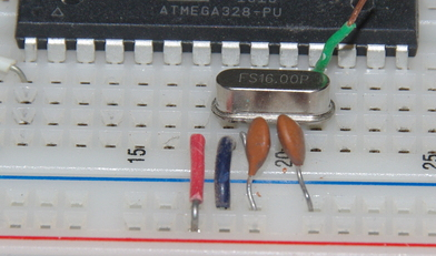
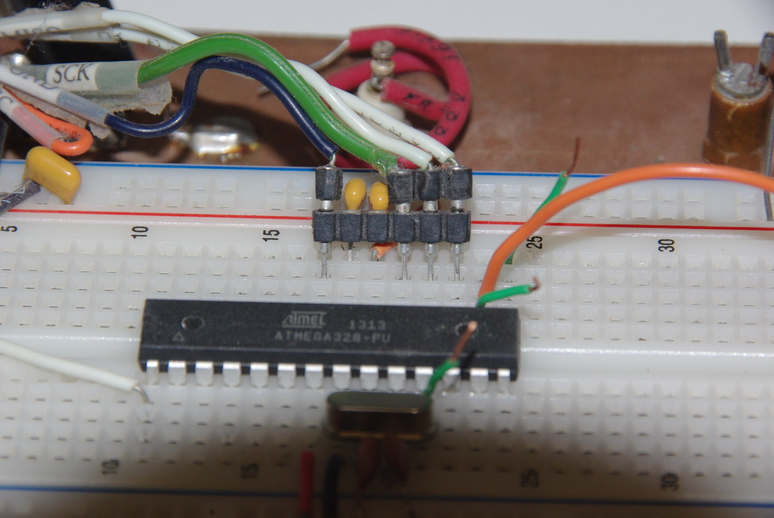
In the above photo, the external caps can be seen that fine tune the frequncy. Sometimes the crystal will change frequency when a circuit is moved from the breadboard to a PC board for a particular design, due to different loading or board trace lengths. Normally, that will not be a problem unless the design is for a timer or perhaps a pulse train for control of something. The red wire is the voltage input to pin 7, the blue wire ground on pin 8.
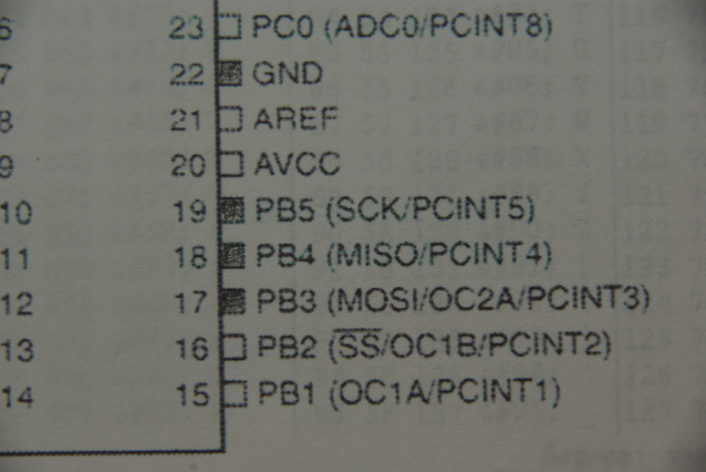
The above image shows the required connections for programming the Atemga 168/328 PDIP package (darkened boxes). Other Atmega chips such as the TQFP (thin quad flat pack) may be programmable through different pins. Here the Serial Peripheral Interface (SPI) pins are used. Pin 17 (MOSI) is input, pin 18(MISO) is output, pin 19 (SCK) is serial clock, and pin 22 (GND) are required in addition with pin 1 (RESET) to read the chip status or load a program into memory. Both the Flash and EEPROM memory arrays can be programmed using the serial SPI bus while RESET is pulled to GND. When programming the EEPROM, an auto-erase cycle is built into the self-timed programming operation (in the Serial mode ONLY) and there is no need to first execute the Chip Erase instruction. The Chip Erase operation turns the content of every memory location in both the Program and EEPROM arrays into 0xFF. Using ‘make’ with a makefile automates all this, including programming the chip using ‘avrdude’, so it’s not necessary to be too concerned with the nitty gritty details.
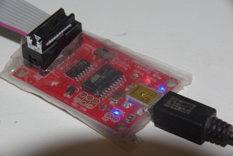
For programming the various chips, I prefer the AVR Pocket Programmer board (USBTINY) as it is small, easy to connect, and has indicators showing the status. Connections are also simple as it is powered from the computer with a USB cable and has cables for connecting to the breadboard (with homemade adapters). The adapters I have built to allow easier connections are plugged into the breadboard, although simple jumper wires can be used for each required pin. The plastic covering on the programmer is to prevent unintended shorts when lying around on the workbench!
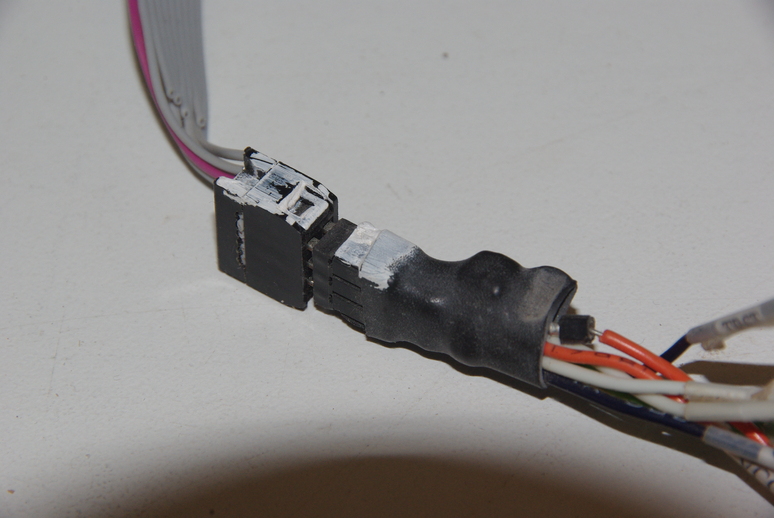
As the photo shows, the adapter is built using a pin strip with a gap skipping the AREF (ADC reference voltage) and AVCC (ADC supply voltage) pins.The ADC is the analog to digital converter. From the left pin (GND), the next pins are the serial clock (SCK), data output (MISO), and data input (MOSI). The advantage of the adapter is less chance of plugging into the wrong place. Another wire (not shown) on the adapter runs to pin 1 (RESET). Notice that by using separate pin strip pins that plug into the pin strip, these can be removed and used where a particular chip has the programming pins in different locations.
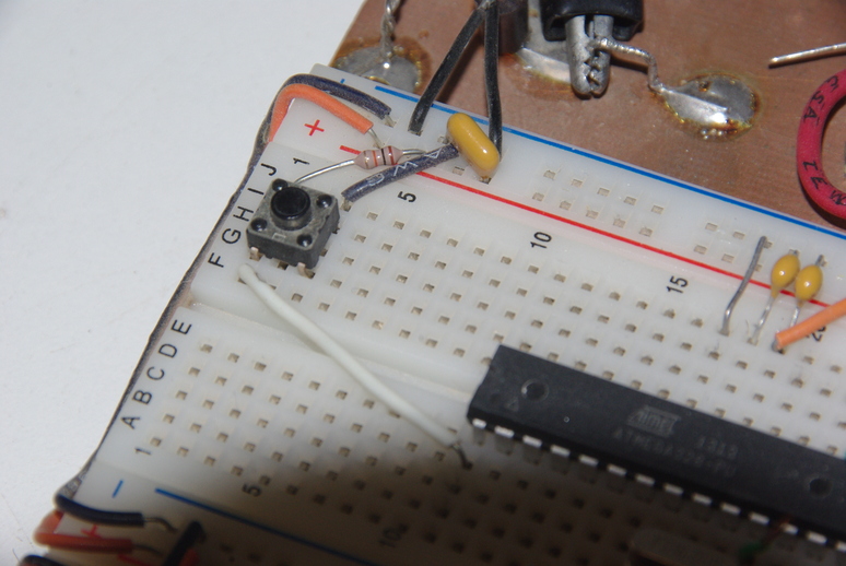
The RESET circuitry is shown above and consists of a 10K ohm pullup resistor connected from the power to pin 1 and a normally open (NO) switch that shorts the low side of the resistor to ground. Attempting to short the power rail side could cause fireworks! The right side of the photo shows the ground jumper and two caps on the AREF and AVCC pins, used to provide some noise supression for the ADC circuitry.
From the command line, the following line can be used to check the chip status.
avrdude -p m328 -c usbtiny -P usb -v
The ‘-p’ identifies the type of chip (such as the m168, m328, etc.) and the ‘-c’ would be the programmer used.
The only productive way to effectively program the Atmega chips is to download copies of the datasheet manuals for the chip(s) you may be interested in working with. One source is from https://ww1.microchip.com.
Atmega 48/88/168 complete datasheet PDF file ~ 6.5 MB filesize.
Atmega48/88/168 summary datsheet PDF file ~ 400KB filesize.
One simple use might be hooking a LCD (liquid crystal display) to the atmega to read voltage inputs if using the ADC, or keep track of events, or as a counter, for example. One of the easier displays to use are ones that use the “standard” HD44780 controller chip such as this 16-character, 2-line display shown below.
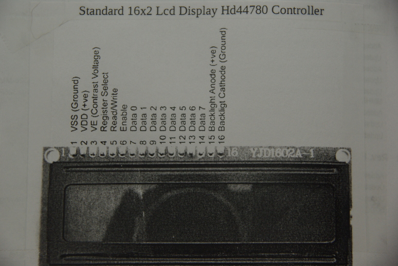
Connections are reduced by using only four data lines instead of eight, thereby saving the additional microcontroller port connections for something else. A 10K ohm pot is connected to the display to control brightness and contrast. Other pin connections are shown in the diagram below.
What’s really handy is the AVR software installation includes the libraries for the HD44780 controller. So by setting a few simple things in the HD44780.h file, such as whether using 4 or 8 data lines, CPU frequency, and then including that header file in your software program, you are ready to rock and roll! If you decide to use the Arduino IDE, those things can be set by selecting built-in options, I think. As I am not familar with Arduino functionality I cannot describe the procedures for that.
For doing these things from the command line, it is as simple as editing a template makefile to configure for your setup, writing your C program using your favorite editor, running ‘make writeflash’ to compile and load the program into your chip, and enjoy! Tutorials and templates are found in many places on the internet, too many to list here!
We thank God for all that we have, including the time and resources to do things like this! We pray that you stay safe during this ongoing pandemic, and remember to wear a mask when out and about! God Bless you, and have a great day!