LoRa Beam Antenna
Having had the Lora transmitter going for quite some time, I have discovered the signal has several groves of trees to go through directly, plus a distance of about 1/4 mile. Given the hype that LoRa is long distance, I was a bit surprised at the short distance that the signal is capable of. This is with an output of about +17 dBm from the transceiver module, into a 1/4 wave vertical antenna. This is, of course, knowing that a certain dBm signal can go only so far, regardless of the transmitting format. So it mostly comes down to how sensitive is the receiver. And that is where a particular encoding format comes into play, along with the redundancy factor.
So, obviously, something different has to be done! The trees are Juniper and Pinon trees, which have quite dense needle/leaf structure. Also, making a totally non-scientific observation, the needles on those trees are similar in length to the sub-multiple wavelength at 915 MHz, which may or may not affect signal absorption.
After looking around, I decided to build a directional antenna, as the signal had only to be directed toward the stationary receiver location. The obvious answer would be a Yagi/Uda antenna structure by DL6WU. I decided to use a 7-element yagi, which should give about 12 dBi gain over a non-directional antenna.
I decided to investigate 3D printing the boom, instead of using a metal boom. 3D printing the boom myself allows spacing the elements as necessary. I used the app Cantennator, which allows setting such things as boom-type, cross-section, driven element type, and element shape.
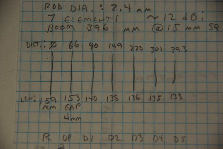
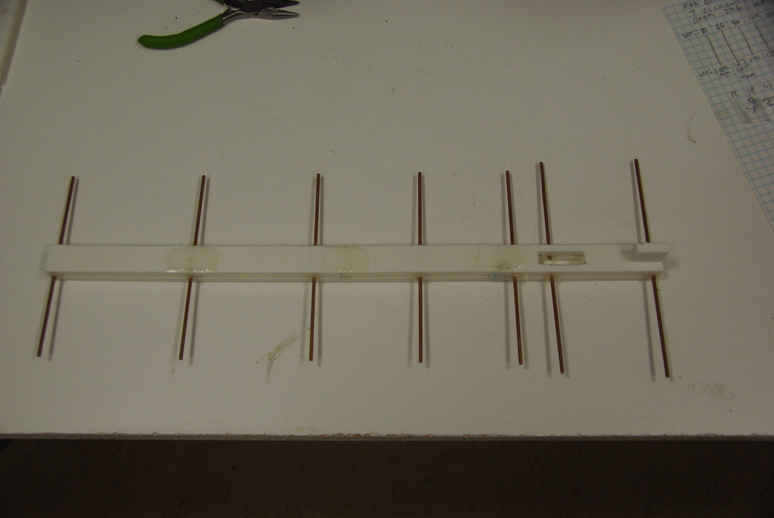
The calculated antenna dimensions and spacing (in millimeters), using a square isolated boom (plastic is insulated…) and 2.4 mm diameter elements (copper coated steel brazing rods), with a non-folded driven element are shown above. The element spacing numbers are all from the reflector element forward. The lengths for all the elements are shown. The driven element is the full length, including the 4 mm gap, which is cut from the center after the element is measured and cut.
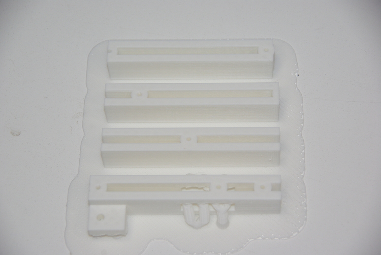
It was simplicity itself to design the boom length and holes for each element using OpenSCAD, importing to Ultimaker Cura to slice, then exporting to a GCODE file to print on the 3D printer. The 3D printer is limited in printing size, so I had to cut the OpenSCAD design into four lengths for printing. The tab on the bottom piece is for mounting. The holes for elements were made longer for more support. This, then, required the actual boom width to be made wider for easier printing.
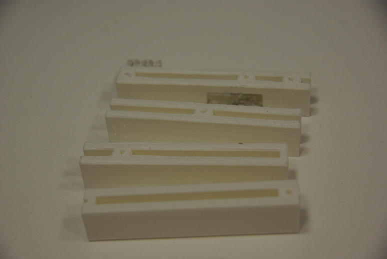
Once removed from the platform, each piece must be cleaned a bit to remove the supports used for horizontal areas. In my case, this required a bit of filing in the areas where the driven element is mounted and the tab for the boom mount.
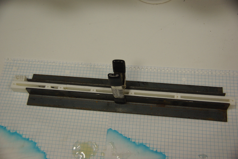
Next is gluing the individual boom pieces into one ~16 inch boom. For additional strength, I used strips of the printing platform (raft) to bridge each joint, as a butt-glued joint is not the strongest design. After drilling out the holes using a 2.5 mm drill, I centered each element and hot-glued in place.
For the driven element, mounted in the boom cutout, I first removed 4 mm from the center, then positioned the elements equally before hot-gluing, ensuring the 4 mm spacing was accurate.
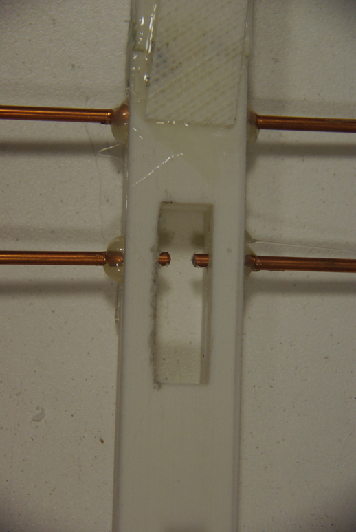
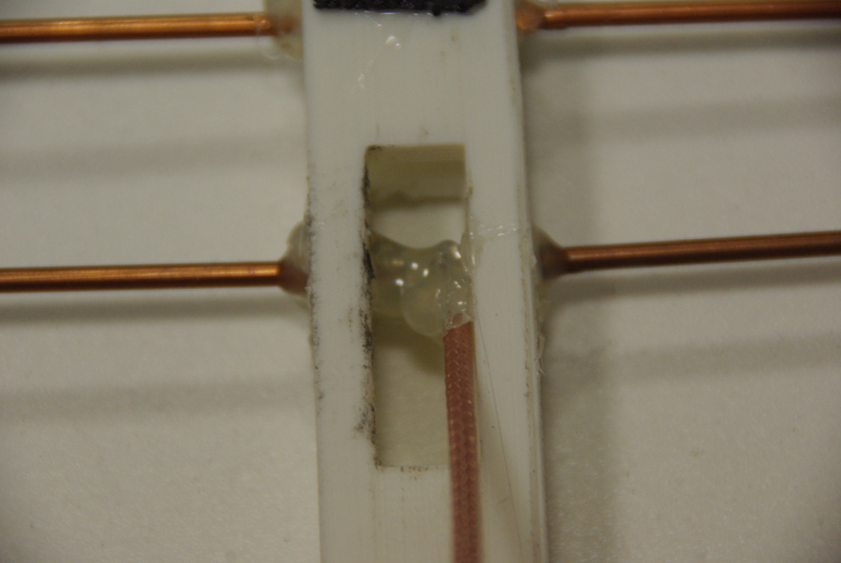
I used mini-coax for the driven element, as it is small and good for UHF frequencies, and more importantly, small enough to fit into the slot of the tiny 915 MHz beam. After the coax is mounted, it must be sealed from the weather. Again, I used hot glue to seal all the joints.
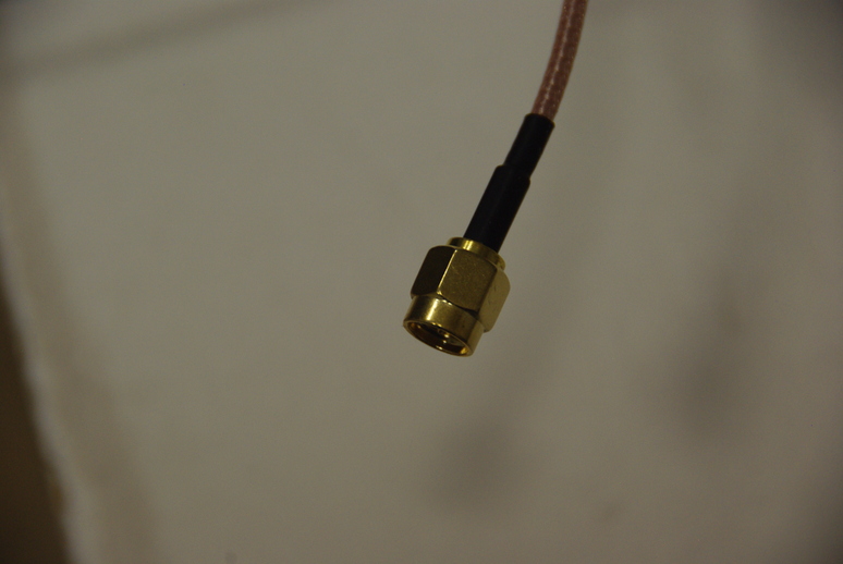
The LoRa module uses a SMA1 connector, so the attached antenna coax cable has a SMA male connector to connect directly to the module.
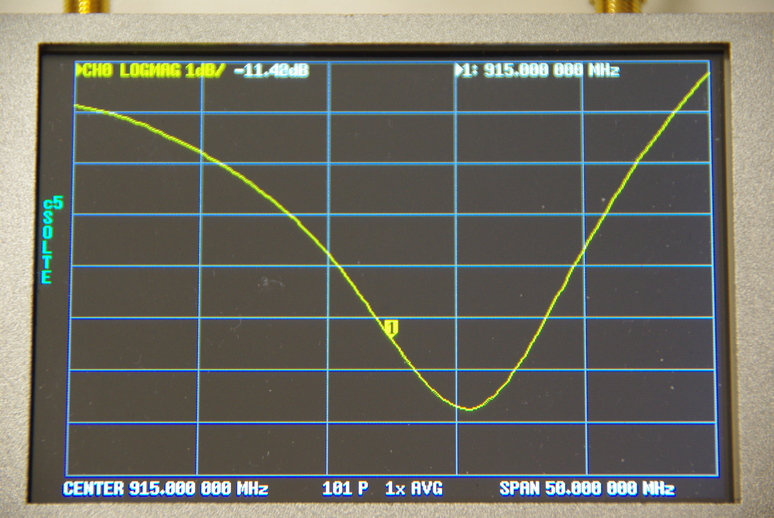
For this prototype version, I made no attempt to clean up the element ends by sanding, as they were somewhat ragged from being cut with a pair of fence pliers. Even so, the preliminary results are not too shabby. Sanding the ends smooth would only raise the resonant frequency higher, so I will leave the ends alone. This image is made using a NanoVNA V2 Plus4 vector network analyzer, and shows data close to the design parameters, especially for a somewhat rough construction.
Installing the beam antenna in place of the 1/4 wave antennas previously employed, has provided a significant signal-to-noise (S/N) ratio, and has improved the reliability of the packet data sent, overcoming the signal absorption of the intervening dense tree cover.
And that wraps up this update on the LoRa adventure. Other posts may follow. We thank God for the ability and knowledge to overcome these problems. Praise God!
Footnotes
SubMiniature version A (SMA) connectors are most commonly used in microwave systems, hand-held radios, mobile telephone antennas and WiFi antenna systems.↩︎